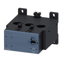
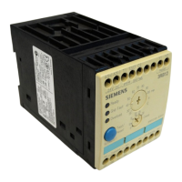
The Siemens 3RB12 is an electronic overload relay designed to protect electrical equipment, such as three-phase AC motors and transformers, using three distinct protection mechanisms.
Function Description
Overload Protection: The 3RB12 continuously compares the actual motor current with a user-defined set current. This comparison and evaluation are performed by an integrated microprocessor, ensuring precise overload detection.
Thermistor Protection: For enhanced thermal protection, the device incorporates PTC thermistors within the motor windings. These thermistors monitor the motor's temperature. If the temperature exceeds a predefined threshold, the relay triggers a trip, preventing thermal damage to the motor.
Earth-Fault Protection: The 3RB12 offers two types of earth-fault detection:
- Internal Earth-Fault Detection: Available in specific versions, this feature is suitable for three-wire systems.
- External Earth-Fault Detection: For applications requiring external monitoring, the device can be connected to an external summation current transformer (3UL22). This option supports both three-wire and four-wire systems.
Important Technical Specifications
General:
- Degree of Protection (IEC 60529): IP 20 for devices 70 mm wide, IP 00 for devices > 70 mm wide.
- Shock-Proof: Conforms to DIN VDE 0106, Part 100.
- EMC (Electromagnetic Compatibility):
- Pulse packets (burst): IEC 61000-4-4, 2 kV
- Discharge of static electricity: IEC 61000-4-2, 8 kV
- Radiated high-frequency fields: IEC 61000-4-3, 3 V/m
- Surge voltage: IEC 61000-4-5, 2 kV
- Permissible Ambient Temperature: -25 to +70 °C
- Storage Temperature: -40 to +80 °C
Weight:
- 70 mm devices: 0.6 kg
- 120 mm devices: 1.0 kg
- 145 mm devices: 1.9 kg
- 230 mm devices: 3.2 kg
Rated Control Supply Voltage:
- AC: 0.85 to 1.1 x Us; 2 VA (where Us is the rated control supply voltage)
- DC (24 V): 0.85 to 1.2 x Us (DIN 19 240); 2W
Main Circuit:
- Frequency: 50/60 Hz
- Rated Insulation Voltage (Ui): 1000 V (for 3RB1246: 690 V)
- Tripping Limit Values (three-pole symmetrical overload):
- Tripping current: 110...120% x Ie (where Ie is the set current)
- Tripping time: < 20 min
Auxiliary Circuit:
- Contacts: 2 x (1 NO and 1 NC)
- Electrical Isolation: Auxiliary switch is potential-free.
- Rated Insulation Voltage (Ui): 300 V
- Switching Capacity (IEC):
- AC-15: 6A/24V; 6A/120V; 3A/230V
- DC-13: 2A/24V; 0.55A/60V; 0.25A/125V
- Switching Capacity (UL/CSA): B300, R300
Short-Circuit Protection:
- Main Circuit: Short-circuit protection with fuses for motor feeders with short-circuit currents up to 50 kA at 690 V, 50/60 Hz (refer to catalog for specific data).
- Control Circuit:
- Fuse links, duty class gL/gG: 6 A
- Quick-acting: 10 A
- Protective circuit-breaker: 1.6 A (C characteristic)
Thermistor Protection:
- Sensor Connection: Thermistor sensor in the motor connects to terminals T1/T2.
- Total Cold Resistance (Rcold): 1.5 kΩ
- Measuring Circuit Loading: ≤ 5 mW (at Rcold = 1.5 kΩ)
- Voltage at Sensor Circuit: ≤ 2 V (at Rcold = 1.5 kΩ)
- Response Value: 2.7 to 3.1 kΩ
- Return Value: 1.5 to 1.65 kΩ
Earth-Fault Protection (based on sinusoidal fault currents of 50/60 Hz):
- External: Summation current transformers 3UL220.-.A are connected to terminals C1/C2. Pick-up delay is 200 ms ≤ t ≤ 500 ms.
- Internal:
- With motor current between 0.3 and 2 times the set current: device trips at an earth-fault current of 30% of the set current.
- With motor current between 2 and 8 times the set current: device trips at an earth-fault current of 15% of the set current.
- Pick-up delay: 0.5 to 1 seconds.
Usage Features
Installation:
- Mounting Position: Any.
- 70 mm Devices:
- Snap-on mounting on 35 mm mounting rail (EN 50 022).
- Screw mounting using inserted lugs (accessory 3RB1900-0B).
- 120 mm, 145 mm, and 230 mm Devices: Screw mounting integrated into the casing.
- 120 mm Devices (additional): Baseplate for snap-on fastening on 75 mm mounting rail (accessory 3UF1900-0J).
Main Conductor Connection:
- Current Range up to 100 A:
- For rated motor currents from 1.25 A to 100 A: Insert motor leads per phase through openings (x).
- For rated motor currents less than 1.25 A: Insert motor leads per phase through openings (x), loop them back through opening (y), and re-insert through openings (x) to create two loops. A table specifies the number of loops for various rated motor currents.
- The device setting current (Ie) is calculated as Ie = n x IN (where n is the number of loops and IN is the rated motor current).
- Current Range 50 A to 820 A (Busbar Connection):
- Uses M8, M10, or M12 screws depending on the device type and conductor size.
- Tightening torques range from 10 to 35 Nm (89 to 310 lb.in).
- Tag termination sizes vary from 20x4 mm to 40x8 mm.
Auxiliary Conductor Connection:
- Supports finely stranded conductors with or without end sleeves (0.5 to 4 mm²) and solid conductors (0.5 to 2.5 mm²).
- Uses connecting screws (0.8x4...5.5 mm) with Pozidriv 2.
- Tightening torque: 0.8 to 1.2 Nm (7 to 11 lb.in).
Thermistor Sensor:
- A link (A) is present upon delivery. This link must be removed when connecting the sensor.
Connection Scheme:
- Circuit diagrams are provided for automatic and remote resets.
- Includes facility for connecting the 3UL22 summation current transformer for external earth fault monitoring.
Operation:
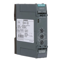
- Setting the Current: Use the current setting range knob to adjust the appropriate current.
- Adjusting Tripping Classes:
- The motor, leads, and contactor must be rated for the selected class (Class 10 as delivered).
- Check and correct the class setting before initial start-up.
- Use the class changeover switch to select the appropriate tripping characteristic (refer to graphic section Fig. VII).
- In case of unsymmetry > 40% (NEMA) or phase failure, tripping occurs as shown in Fig. VIII. Characteristics apply to a cold start; tripping times (tA) are reduced for starting under full load.
- The current range setting knob and class changeover switch can be protected from tampering using the sealable cover plate 3RB1900-0A.
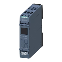
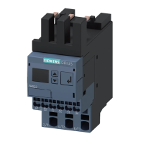
Device Statuses (via LEDs and Auxiliary Switches):
- Device Ready for Operation (no overload, not tripped):
- Ready LED: Green steady light.
- Auxiliary switch: 95/96, 05/06 closed; 97/98, 07/08 open.
- Overload Alarm (limit tripping current reached, tripping imminent):
- Overload LED: Red flashing light.
- Auxiliary switch: 05/06 open; 07/08 closed.
- Overload Trip/Thermistor Trip:
- Overload LED: Red steady light.
- Auxiliary switch: 95/96 open; 97/98 closed.
- Earth Fault Alarm:
- Gnd. Fault LED: Red steady light.
- Auxiliary switch: 05/06 open; 07/08 closed (for 3RB12..-...0, 3RB12..-...2); 95/96 open; 97/98 closed (for 3RB12..-...1, 3RB12..-...3).
- Device Not Ready for Operation (control voltage failure):
- Ready LED: Dark.
- Auxiliary switch (monostable version): 95/96, 05/06 open; 97/98, 07/08 closed.
- Auxiliary switch (bistable version): Switching statuses are retained.
Test Function:
- The Test/Reset button allows checking device status.
- Press for up to 2 seconds: LEDs indicate current status (Ready, Gen. Fault, Overload). Auxiliary switching elements remain unchanged.
- Press after 2 seconds: LEDs indicate status, and auxiliary switching elements reset.
- Press for > 5 seconds: LEDs indicate status, and auxiliary switching elements reset.
- A test with a duration of less than 5 seconds can be performed during operation without changing outputs in a fault-free state.
Reset Function:
- Overload Trip: Can be reset immediately by briefly pressing the test/reset button or by remote reset (briefly pressing button at Y1-Y2). Automatic reset (bridging Y1-Y2) is also an option. After an overload trip, the device can be reset to operating mode after five minutes.
- Thermistor Trip: Can be reset after the temperature has reached 5 K below the response temperature.
- Earth Fault: Can be reset immediately by briefly pressing the test/reset button or by remote reset. Automatic reset is not effective for earth faults.
- If both thermistor and overload have tripped simultaneously, the longer reset phase applies.
- The protection functions are not impeded by holding down the test/reset button.
Maintenance Features
- Installation and maintenance should only be performed by technical personnel.
- Always follow the operating instructions.
- WARNING: Hazardous voltage can cause electrical shock and burns. Disconnect power before proceeding with any work on this equipment.