Installation
12 3ZX1012-0RB12-1AA1
English
2Installation
For dimension drawings, see graphics section, Fig. I
and II.
Mounting position: any
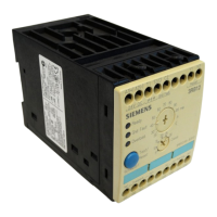
Mounting of 70 mm devices:
■ Snap-on mounting on 35 mm mounting rail in con-
formity with EN 50 022 or
■ srew mounting by means of inserted lugs as
accessory (3RB1900-0B).
Mounting of the 120 mm, 145 mm und 230 mm
devices:
■ Crew mounting integrated in the casing.
■ In addition for 120 mm size:
Baseplate for snap-on fastening on 75 mm mount-
ing rail (3UF1900-0J) available as accessory.
3 Connection
3.1 Main conductor connection
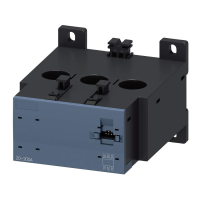
3.1.1 Current range up to 100 A
■ Rated motor currents from 1.25 A to 100 A:
Insert the motor leads per phase through the open-
ings (x) in the unit (see graphics section, Fig. Ia).
■ Rated motor currents less than 1.25 A:
Insert the motor leads per phase through the open-
ings (x), take them back through the loop opening (y)
and insert them again through the openings (x). You
will produce two loops in this way (see graphics sec-
tion, Fig. Ia).
The following table lists the number of loops for the
various rated motor currents.