User´s Guide Power Rail Booster Version 12/2005
Copyright © Siemens AG 2005 All rights reserved. 6ES7 972-4AA02-0XA0 Page 30 of 49
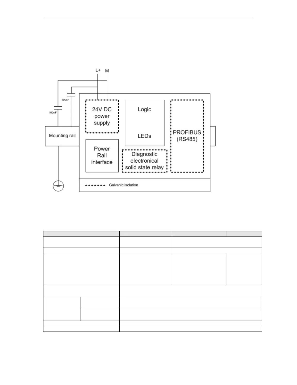
6.3.2 Interfaces and Connector Pin Assignment
6.3.2.1 Graphical interface diagram, galvanic isolation
The PRB is equipped with a number of interfaces, which are shown in the diagram
below.
Fig. 19: Overview of interfaces on the Power Rail Booster
6.3.2.2 Wiring guidelines for interfaces
The following figure gives an overview about the wiring of the PRB interfaces.
Wiring guidelines for ... Power 24 V DC Power Rail A / B SF OUT
Usable wires / cables Unshielded / shielded
solid / flexible
Unshielded / shielded
solid / flexible
Shield Not necessary Not necessary
Wire routing No special requirement Carry functional ground
parallel (for example:
additional wire,
connected on both sides)
Preferably use of 3-/5-
wired cables
No special
requirement
Connectable cross
sections for solid wires
0,2 to 2,5 mm²
Without
sleeve
0,2 to 2,5 mm² Connectable
cross sections
for flexible wires
With
sleeve
0,25 to 2,5 mm²
Skinning length 10 mm
Sleeves See DIN 46228
Fig. 20: Wiring guidelines for the interfaces of the Power Rail Booster
Artisan Technology Group - Quality Instrumentation ... Guaranteed | (888) 88-SOURCE | www.artisantg.com
 Loading...