User´s Guide Power Rail Booster Version 12/2005
Copyright © Siemens AG 2005 All rights reserved. 6ES7 972-4AA02-0XA0 Page 31 of 49
6.3.2.3 Connecting the Power Rail interface
The connection is established via the 15-pin terminal block on the front of the
PRB.
Æ Because of their low capacitance, all cables to the contact rail on the Power
Rail side, such as incoming cables and connecting cables, should be
PROFIBUS cables. In principle, however, it is also possible to use other cable
types, in which case the maximum cable length must match the cable
capacitance.
Pin - Nr.
Name Function
10 A1 Contact rail A, first sliding contact
11 A2 Contact rail A, second sliding contact
12 B1 Contact rail B, first sliding contact
13 B2 Contact rail B, second sliding contact
14
Functional ground
15
Functional ground
Fig. 21: Terminal assignment for the Power Rail interface
6.3.2.4 Connecting the PROFIBUS interface
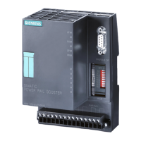
PRBs are equipped with an electrical port with RS 485 level. This port takes the form
of a 9-pin D Subminiature socket with screw-type locking mechanism. Bus lines A
and B are galvanically isolated from the 24 V supply voltage and the Power Rail
voltage. The port is located on the front of the PRB.
Æ For the PROFIBUS DP side, the installation guidelines contained in the
"SIMATIC NET PROFIBUS Networks" manual apply.
Æ Connect the RS 485 bus segment using a PROFIBUS bus connector. If the PRB
is located at the beginning or end of a bus segment, the bus terminator on this
interface must be switched on.
Æ All PROFIBUS bus connectors in the network must be screwed tightly into the RS
485 interface.
Æ Make sure that the bus segment connected to the RS485 interface is terminated
at both ends.
Pin - Nr.
Name Function
1 n.c. Reserved
2 n.c. Reserved
3 RxD/TxD-P Data line B
4 RTS Request to send
5 GND Ground
6 VCC Supply voltage
7 n.c. Reserved
8 RxD/TxD-N Data line A
9 n.c. Reserved
Fig. 22: Terminal assignment for the PROFIBUS RS485 interface
6.3.2.5 Connecting the operating voltage
The operating voltage is connected via the 15-pin terminal block on the front of the
PRB. The connection is protected against polarity reversal. Pins 1-2 and pins 3-4 are
jumpered internally.
Artisan Technology Group - Quality Instrumentation ... Guaranteed | (888) 88-SOURCE | www.artisantg.com
 Loading...