User´s Guide Power Rail Booster Version 12/2005
Copyright © Siemens AG 2005 All rights reserved. 6ES7 972-4AA02-0XA0 Page 34 of 49
7 LED Display and Troubleshooting
7.1 Diagnostic Displays for the Power Rail Booster
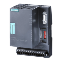
The front of the Power Rail Booster features 6 LEDs for quick diagnosis of faults and
operating states. The Table below describes the faults and operating states indicated
by the LEDs and their causes.
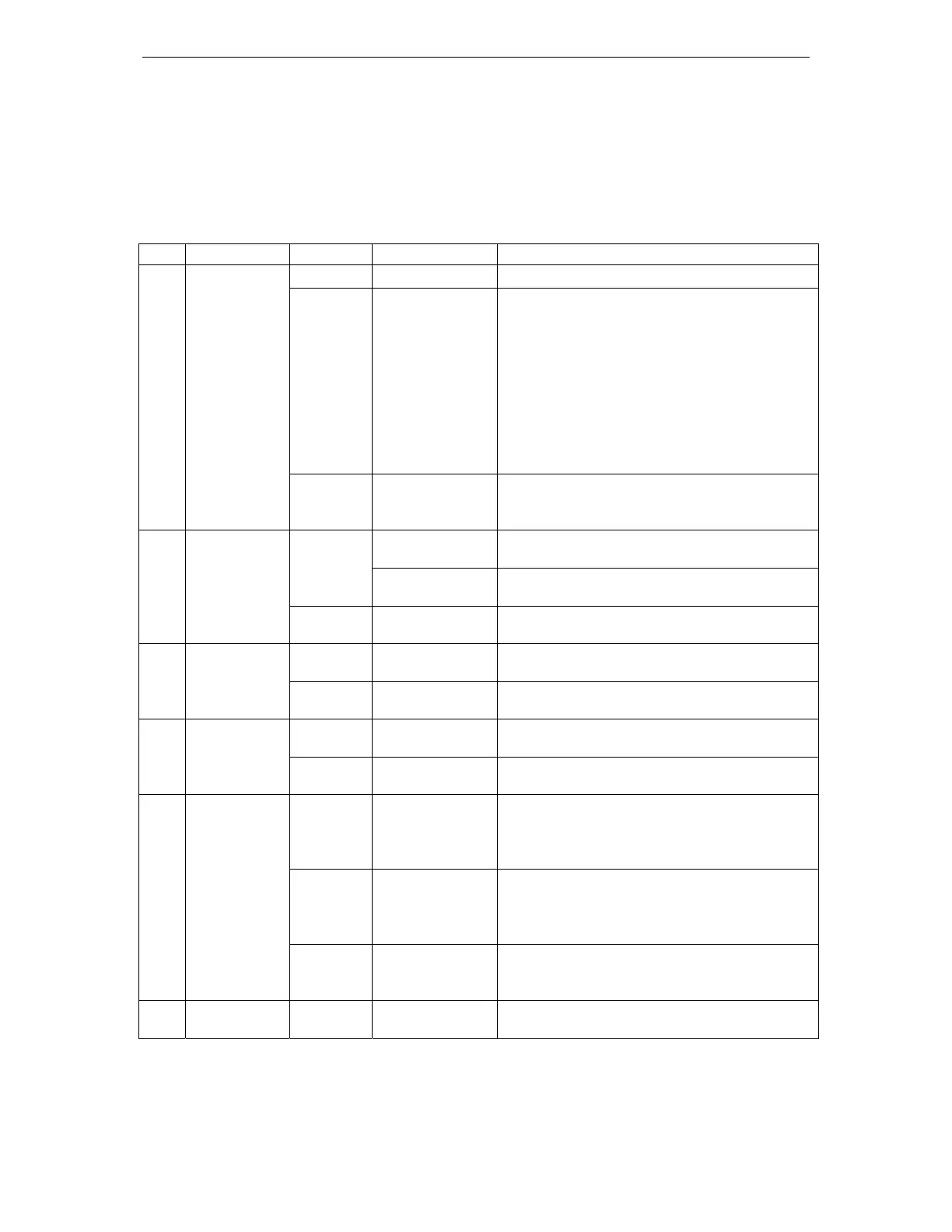
LED Meaning Display State Cause/Remarks
Off No fault
Red Group error - Short circuit on Power Rail.
- Line interruption on PROFIBUS (feed
booster only)
- Line interruption on Power Rail (moving
booster only)
- Baud rate not found or invalid baud rate
- Baud rate lost following invalid message
frames (frame collision on the bus)
- Shutdown due to excessively high
temperature
SF PRB
Group error
Yellow
flashing
(2Hz)
Warning - Warning threshold exceeded for output
temperature
No supply
voltage
24V DC supply voltage not connected Off
Internal logic
not ready
PRB defective
ON PRB ready
Green Supply voltage
OK
Off - No message frames received on
PROFIBUS side
DP Bus activity
PROFIBUS
On
Flickers
- No message frames received on
PROFIBUS side
Off - No message frames received on Power
Rail side
PR Bus activity
Power Rail
On
Flickers
- No message frames received on Power
Rail side
Off Temperature
within
permissible
range
Safe, reliable communication ensured for
this parameter
Red
Shutdown
due to
overtemperature
- Output temperature too high. Reliable,
safe communication no longer ensured.
Power section shut down following
termination of last message frame
ϑ
Temperature
Yellow
flashing
(2Hz)
Warning due to
overtemperature
- Output temperature just before critical
range. Safe communication is still
possible.
C Reserve Off Not currently used
Fig. 28: Possible LED displays and their causes
Artisan Technology Group - Quality Instrumentation ... Guaranteed | (888) 88-SOURCE | www.artisantg.com
 Loading...