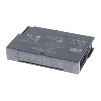
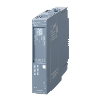
2AI I 4WIRE ST analog electronic module (6ES7134-4GB11-0AB0)
Manual, 04/2007, A5E01076100-01
19
Connecting
5
5.1 Connecting measuring sensors
Introduction You can connect current transmitters to the 2 AI I 4WIRE analog input module to act as:
● Connecting 4-wire transmitters.
In this chapter you will find out how to connect the measuring encoders and what to watch
out for when doing so.
Cables for analog signals
You should use shielded and twisted-pair cables for the analog signals. This reduces the
effect of interference. You should ground the shield of the analog cables at both ends. If
there are differences in potential between the cable ends, an equipotential bonding current
that may interfere with the analog signals will flow across the shield. If this is the case, you
should only ground the shield at one end of the cable.
Analog input modules
The analog input modules are electrically isolated:
● Between the logic and backplane bus
● No isolation: Link between M
ANA
and central grounding point
Note
Ensure that this difference in potential U
ISO
does not exceed the permitted value. If there
is a possibility of exceeding the permitted value, establish a connection between terminal
M
ANA
and the central grounding point.
Connecting measuring encoders to analog inputs
There can be only a limited potential difference U
CM
(common mode) between the measuring
lines M- of the input channels and the reference point of the measuring circuit M
ANA
. To
ensure that the permitted value is not exceeded, you must take different steps depending on
the whether the encoders are isolated or non-isolated. The steps you have to take are
described in this chapter.

 Loading...


