Do you have a question about the Siemens 6ES7151-1BA02-0AB0 and is the answer not in the manual?
Explains the manual's scope, objectives, and content structure for users.
Outlines the necessary prior knowledge for users to understand the documentation effectively.
Information on contacting Siemens representatives for assistance and further information.
Details on how to reach Siemens technical support services via phone and web.
Details the core features and capabilities of the IM151-1 HIGH FEATURE module.
Covers limitations on module usage, compatibility, and installation requirements.
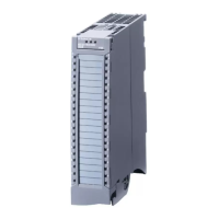
Shows physical connections for power supply and PROFIBUS DP interface.
Illustrates the module's internal architecture and key connection points.
Lists key specifications like dimensions, weight, voltage, current, and protocols.
Explains LED displays for status/errors and the procedure for updating module firmware.
Lists all available parameters for the IM151-1 HIGH FEATURE interface module.
Details critical settings like interrupt modes, bus length, and startup options.
Covers settings for module slot management and diagnostic interrupt behavior.
Focuses on cycle synchronization and time settings (Ti, To) for data transfer.
Fundamental principles of achieving reproducible response times with synchronous operation.
Step-by-step guide for setting up cycle synchronization parameters in PROFIBUS DP.
Describes the operational mechanism of using placeholder modules for future configurations.
Steps to assign parameters for managing slot configurations with placeholder modules.
Explains the alternative method for handling optional modules without using placeholders.
Steps to configure the system for option handling without placeholder modules.
Details how to access and read specific module identification information.
Explains the meaning of the SF, BF, and ON LEDs for module status and error indication.
Describes how the system responds to diagnostic messages in DPV0 and DPV1 modes.
Methods for reading, interpreting, and evaluating diagnostic data using STEP 7 software.
Details the layout and components of the slave diagnostic information frame.
Covers identifier-related, module status, and channel-specific diagnostic information.
Details interrupt types, structure, and data records for system events.
Identifies invalid configuration states that lead to station failure or communication issues.
Illustrates the various timing aspects between the DP Master and the ET 200S system.
Provides a formula to estimate the response time in non-isochronous operation.
Covers timing for digital input and output modules, including input/output delay.
Explains conversion, cycle, and settling times for analog input and output modules.
Covers response times for IQ-SENSE and technology modules.
| Number of Inputs | 16 |
|---|---|
| Input Voltage | 24 V DC |
| Signal Level | 24 V DC |
| Supply Voltage | 24 V DC |
| Number of DP Masters | 1 |
| Digital Inputs | 16 |
| Analog Inputs | 0 |
| Analog Outputs | 0 |
| Mounting Type | DIN rail |
| Width | 40 mm |
| Data Transfer Rate | Up to 12 Mbit/s |
| Operating Temperature | 0 to 60 °C |
| Weight | Approx. 400 g |