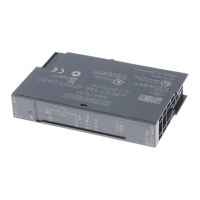
Do you have a question about the Siemens 6ES7521-1BL00-0AA0 and is the answer not in the manual?
Explains safety alert symbols and danger grading for personal safety and property.
Defines personnel qualified to operate the product based on training and experience.
Notes on using Siemens products safely, including transport, installation, and operation.
Lists trademarks and states the publisher's review and liability disclaimer.
Describes the manual's role and its relation to system and function manuals.
Highlights changes from previous versions and explains terminology used.
Provides guidance on industrial security for Siemens products and systems.
Details the use of open-source software in the firmware of I/O modules.
Describes function manuals covering general topics like diagnostics and communication.
Refers to product manuals with detailed module-specific information.
Points to system manuals and online help for configuration and programming.
Links to online support, manual collections, and configuration tools.
Lists technical properties, including input count and voltage, and the part number.
Details module functions and software version dependencies for configuration.
Lists supplied and orderable accessories such as front connectors and labeling strips.
Shows the module's block diagram and terminal assignment for wiring.
Explains how to configure the module in STEP 7 using hardware catalog or GSD file.
Details address assignment for the 1x32-channel configuration.
Details address assignment for the 4x8-channel configurations.
Details address assignment with Module-internal Shared Input (MSI).
Explains the meaning of value status for submodules in MSI configurations.
Shows address space with value status for MSI submodules.
Shows address space for 3rd and 4th MSI submodules with value status.
Points to further information on the module-internal shared input/output function.
Describes the LED displays for status and errors on the DI 32x24VDC BA module.
Explains RUN/ERROR and CHx LED status meanings and provides remedies.
Provides general information, hardware status, and firmware version.
Specifies voltage ranges, power consumption from backplane, and power loss.
Lists input count, configurability, sinking/sourcing input, and input voltage.
Specifies input current, input delay, and delay times for signal transitions.
Provides maximum cable lengths and details for connectable encoders.
Lists available diagnostics functions, interrupts, and indicator LEDs.
Details electrical isolation specifications and operating temperature ranges.
Shows the physical dimensions of the module mounted on a rail.
Shows the physical dimensions of the module with its front cover open.
The SIMATIC S7-1500 / ET 200MP Digital Input Module DI 32x24VDC BA (6ES7521-1BL10-0AA0) is a crucial component within the SIMATIC S7-1500 automation system and the SIMATIC ET 200MP distributed I/O system. This manual provides comprehensive information for commissioning and maintaining these systems, focusing specifically on the digital input module.
The DI 32x24VDC BA module serves as an interface for acquiring digital signals within an industrial automation environment. It features 32 digital inputs, allowing for the connection of a significant number of field devices. A key characteristic of this module is its electrical isolation, which is provided in groups of 16 inputs. This isolation helps to protect the module and the overall system from electrical disturbances and ensures reliable operation. The module is designed to operate with a rated input voltage of 24 VDC, a common standard in industrial control systems. It is versatile enough to accommodate various types of input devices, including standard switches and 2-, 3-, or 4-wire proximity switches, making it suitable for a wide range of applications.
The module supports several configurations, which dictate how its addresses are assigned within the process image of the inputs. In its basic configuration, it operates as a 1 x 32-channel module without value status, where the start address can be freely assigned, and the addresses for individual channels are derived from this start address. For more advanced applications, it can be configured as a 4 x 8-channel module, also without value status. In this setup, the channels are divided into multiple submodules, each with its own freely assignable start address. This submodule division is particularly useful when the module is employed in a shared device scenario, allowing different IO controllers to access specific groups of inputs. Furthermore, the module supports a 1 x 32-channel configuration with value status for module-internal Shared Input (MSI), accommodating up to 4 submodules. In this MSI configuration, channels 0 to 31 are copied to multiple submodules, providing identical input values across different submodules. This enables up to four IO controllers to have read access to the same channels, enhancing flexibility in system design. The value status (Quality Information, QI) in MSI configurations indicates the correctness of the input value, particularly for the 2nd to 4th submodules, where a status of '0' signifies an incorrect value or an unconfigured basic submodule.
The DI 32x24VDC BA module is designed for ease of integration and operation within the SIMATIC S7-1500 and ET 200MP systems. It is compatible with STEP 7 (TIA Portal) for configuration, with specific version dependencies for firmware updates, identification data, module-internal Shared Input, and configurable submodules for Shared Device. Alternatively, it can be configured using a GSD file, providing flexibility for different engineering environments. The module's hardware is also compatible with the DI 16x24VDC BA digital input module, which can simplify spare parts management and system upgrades.
The module's wiring and block diagram are clearly outlined, showing the assignment of channels to input bytes, which is crucial for correct signal routing and programming. Information on wiring the front connector, creating cable shields, and other installation details can be found in the broader S7-1500/ET 200MP system manual, ensuring a robust and well-installed system.
For maintenance and diagnostics, the module incorporates LED displays that provide immediate visual feedback on its operational status and any detected errors. The "RUN" LED indicates the module's operational state, while the "ERROR" LED signals faults. Specific LED patterns communicate various conditions, such as voltage issues on the backplane bus, module startup, readiness, or hardware defects. For instance, a flashing "RUN" LED with an "Off" "ERROR" LED indicates the module is starting up, while a steady "On" "RUN" LED with an "Off" "ERROR" LED signifies that the module is ready. If both LEDs are flashing, it points to a hardware defect, prompting a module replacement.
Additionally, each channel has its own "CHx" status LED, which indicates the status of the input signal. An "Off" "CHx" LED means the input signal status is '0', while an "On" "CHx" LED indicates a status of '1'. These individual channel indicators are invaluable for quick troubleshooting and verification of input signals without requiring additional diagnostic tools.
While the module itself does not offer selectable diagnostics through STEP 7 (TIA Portal), the comprehensive LED displays serve as a primary diagnostic interface. For broader system maintenance and commissioning, tools like the SIMATIC Automation Tool and SIEMENS PRONETA are available. The SIMATIC Automation Tool facilitates bulk operations such as network scanning, address assignment, program downloads, operating mode switchovers, CPU localization via LED flashing, and reading out diagnostic buffers and error information. SIEMENS PRONETA, on the other hand, is designed for PROFINET network analysis during commissioning, offering topology overviews and IO checks to verify wiring and module configuration. These tools, combined with the module's integrated LED diagnostics, provide a robust framework for both initial setup and ongoing maintenance, ensuring the reliability and availability of the automation system.
| Product Type | Digital Input Module |
|---|---|
| Number of Inputs | 16 |
| Input Voltage | 24 V DC |
| Width | 35 mm |
| Height | 147 mm |
| Depth | 129 mm |
| Input Current | 7 mA |
| Electrical Isolation | Yes |
| Mounting Type | DIN rail |
| Supply Voltage | 24 V DC |
| Connection Technology | Screw terminal |
| Operating Temperature | -20 to +60 °C |


