Diagnostics alarms
5.1 Status and error displays
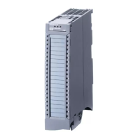
Digital input module DI 32x24VDC BA (6ES7521-1BL10-0AA0)
Manual, 12/2016, A5E32363711-AD
19
Meaning of the LED displays
The tables below explain the meaning of the status and error displays.
Table 5- 1 RUN/ERROR status and error displays
Off
Off
Voltage missing or too low at backplane bus.
• Switch on the CPU and/or the system pow-
er supply modules.
• Verify that the U connectors are inserted.
• Check to see if too many modules are in-
serted.
Module is starting up. ---
On
Off
Module is ready.
Hardware defective. Replace the module.
Table 5- 2 CHx status display
0 = Status of the input signal. ---
1 = Status of the input signal. ---
 Loading...

