Siemens Protection Devices Limited 9
7SG11
Argus
BO 1
BI 1
+ve
-ve
5
6
3
4
BO 2
10
9
8
BO 3
18
17
16
BO 4
11
12
BO 5
19
20
1A
5A
E/F
25
26
27
28
C
B
7
1A
5A
45
46
47
48
1A
5A
49
50
51
52
A
1A
5A
53
54
55
56
BO 6
21
22
BO 7
23
24
Case
earth
+ve
-ve
13
14
15
EXPANSION PCB
Earth
BI 2
+ve
-ve
35
36
BI 3
+ve
-ve
33
34
BI 4
-ve
31
32
BI 5
+ve
-ve
29
30
EXPANSION PCB
BI 2
+ve
-ve
35
36
BI 3
+ve
-ve
33
34
BI 4
-ve
31
32
BI 5
+ve
-ve
29
30
BI 6
+ve
-ve
43
44
BI 7
-ve
41
42
BI 8
+ve
-ve
39
40
BI 9
+ve
-ve
37
38
BO 8
37
38
BO 9
40
41
BO 10
41
42
BO 11
43
44
81
82
83
79
80
A B C
1A
5A
E/F
25
26
27
28
C
B
1A
5A
45
46
47
48
1A
5A
49
50
51
52
A
1A
5A
53
54
55
56
A B C
A B C
83
84
81
82
79
80
A B C
83
84
81
82
79
80
Va
Vb
Vc
Va
Vb
Vc
Dn
Da
S2 S1
P2 P1
Direction of power flow
In the forward direction
Direction of power flow
In the forward direction
P2 P1
S2 S1
Va
Vb
Vc
Dn
Da
Phase-phase connection
- see note 6
Phase-earth
connection
-see note 6
See note 2
See note 5
See note 1
S2 S1
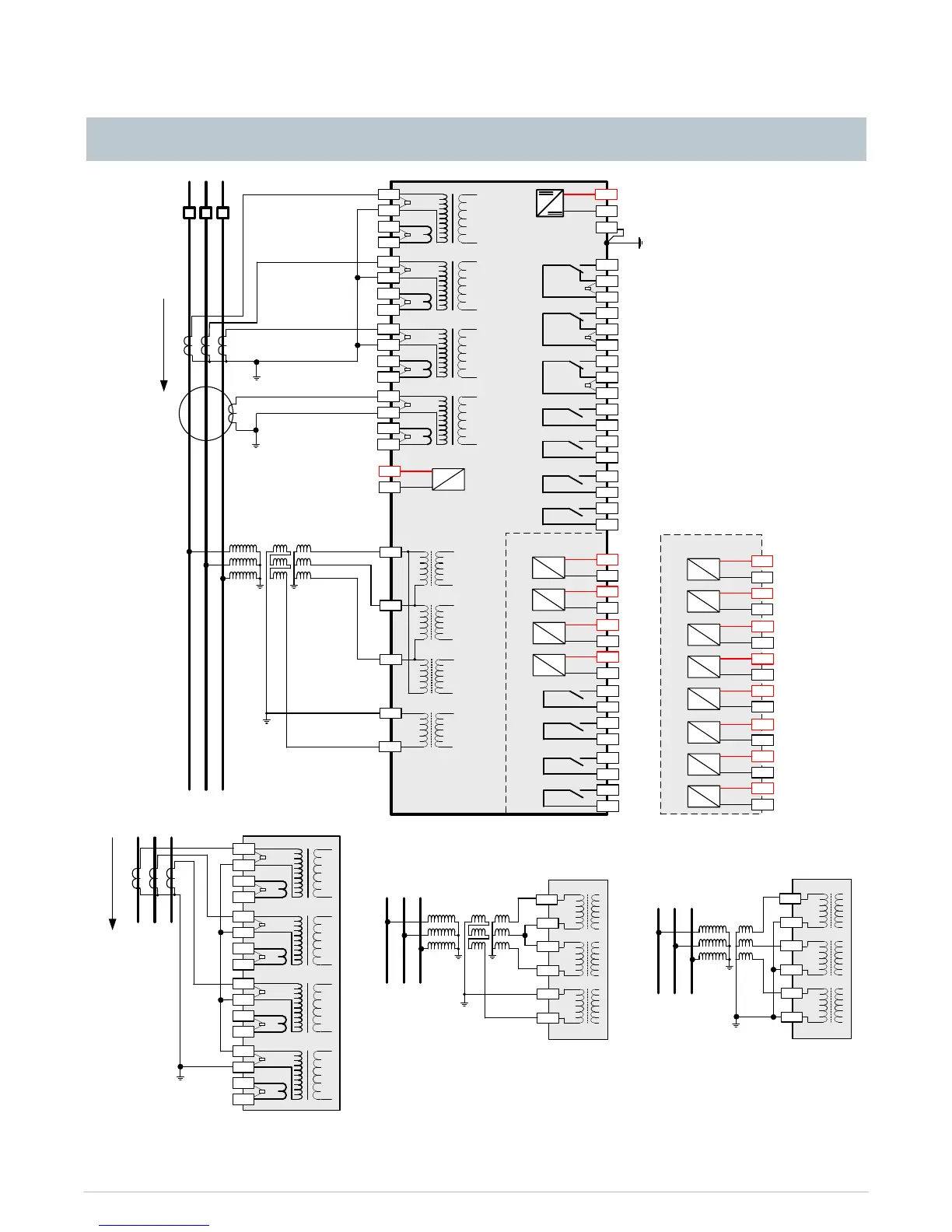
Notes
1) Diagram shows 3PF + SEF model using a
ring core CT. See diagram below for
alternative connection. Other CT mixes also
available.
2) Voltage card fitted only on 7SG112n and
7SG1164 relays. Diagram shows 3 phase and
earth voltage inputs. See diagram below for
alternative voltage input.
3) Optional expansion card, fitted only on
models with 5 binary inputs and 11 output
relays.
4) Optional expansion card, fitted only on
models with 9 binary inputs and 7 output
relays.
5) Diagram shows 3PF + EF model using the
Holmgreen connection. Other CT mixes also
available.
6) Voltage card shown can be fitted only on
7SG1125 relays.
See note 3 See note 4
Fig 3. Connection Diagram for 7SG11 Overcurrent Relay
Connection Diagram
 Loading...


