(1) Description of Operation 7SR224
©2009 Siemens Protection Devices Limited Page 13 of 66
Each LED can be user programmed as hand or self –resetting. Hand reset LEDs can be reset by
either pressing the TEST/RESET► button, energising a suitably programmed binary input, or, by
sending an appropriate command over the data communications channel(s).
The status of hand reset LEDs is maintained by a back up storage capacitor in the event of an
interruption to the d.c. supply voltage.
Standard Keys
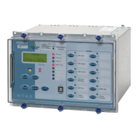
The relay is supplied as standard with five navigation / control pushbuttons and 12 programmable
function keys. The navigation / control buttons are used to navigate the menu structure and control
relay functions. They are labelled:
▲ Increases a setting or moves up menu.
▼ Decreases a setting or moves down menu.
TEST/RESET► Moves right, can be used to reset selected functionality and for LED
test (at relay identifier screen).
ENTER Used to initiate and accept settings changes.
CANCEL. Used to cancel settings changes and/or move up the menu structure
by one level per press.
NOTE: All settings and configuration of LEDs, BI, BO and function keys can be accessed and set by
the user using these keys. Alternatively configuration/settings files can be loaded into the relay using
‘Reydisp’.
Function Keys/ LEDs
The 12 programmable function keys can be configured by the user to initiate selected functions from
the Control menu (INPUT CONFIG > FUNCTION KEY MATRIX).
Each programmable function key has an associated LED. These can be programmed as hand or self
reset and can be illuminated as green, yellow or red (OUTPUT CONFIG > LED CONFIG).
Function keys can be used with Quick Logic.
2.6 CURRENT INPUTS
Four current inputs are provided on the Analogue Input module. Terminals are available for both 1A
and 5A inputs.
Current is sampled at 32 samples per cycle (1600Hz) for both 50Hz and 60Hz system frequencies.
Protection and monitoring functions of the relay use either the Fundamental Frequency RMS or the
True RMS value of current appropriate to the individual function.
The waveform recorder samples and displays current input waveforms at 32 samples per cycle
(1600Hz).
2.7 VOLTAGE INPUTS
Four voltage inputs are provided on the Analogue Input module.
Voltage is sampled at 32 samples per cycle (1600Hz) both 50Hz and 60Hz system frequencies.
Protection and monitoring functions of the relay use fundamental frequency voltage measurement.
The waveform recorder samples and displays voltage input waveforms at 32 samples per cycle
(1600Hz).

 Loading...


