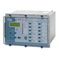
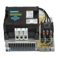
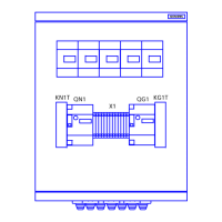
E10 case, 4 CT, 6 VT, 13 Binary Inputs / 14 Binary Outputs, 8 LEDs + 12 keys
1
||||| |
DA
|
E10 case, 4 CT, 4 VT, 13 Binary Inputs / 14 Binary Outputs, 8 LEDs + 12 keys
2
||||| |
C
||
E10 case, 4 CT, 4 VT, 23 Binary Inputs / 22 Binary Outputs, 8 LEDs + 12 keys
3
||||| |
C
||
E10 case, 4 CT, 4 VT, 33 Binary Inputs / 14 Binary Outputs, 8 LEDs + 12 keys
4
||||| |
C
||
E10 case, 4 CT, 6 VT, 23 Binary Inputs / 22 Binary Outputs, 8 LEDs + 12 keys
5
||||| |
DA
|
E12 case, 4 CT, 4 VT, 33 Binary Inputs / 14 Binary Outputs, 16 LEDs + 12 keys
6
||||| |
C/E A
|
E12 case, 4 CT, 4 VT, 33 Binary Inputs / 30 Binary Outputs, 16 LEDs + 12 keys
7
||||| |
C/E A
|
E12 case, 4 CT, 4 VT, 43 Binary Inputs / 22 Binary Outputs, 16 LEDs + 12 keys
8
||||| |
C/E A
|
||||| ||||
Measuring Input
8
|||| ||||
1/5 A, 63.5/110V
2
|||| ||||
|||| ||||
Auxiliary Nominal Voltage
9
||| ||||
30 to 220V DC, binary input threshold 19V DC 22W A
||| ||||
30 to 220V DC, binary input threshold 88V DC 22W B
||| ||||
||| ||||
Region Specific Functions
10
|| ||||
Region World, 50/60Hz, language English, Reyrolle fascia A
|| ||||
Region World, 50/60Hz, language English, Siemens fascia
B
|| ||||
Region USA, 60/50Hz, language English - US (ANSI) (language changeable), Siemens fascia
C
|| ||||
|| ||||
Communication Interface
11
| ||||
Standard version - included in all models, USB front port, RS485 rear port
1
| ||||
Standard version - plus additional rear F/O ST connectors (x2) and IRIG-B
2
| ||||
Standard version - plus additional rear RS485 and IRIG-B
3
| ||||
Standard version - plus additional rear RS232 and IRIG-B
4
| ||||
| ||||
Protocol
12
||||
IEC 60870-5-103
0
||||
IEC 60870-5-103 and Modbus RTU (user selectable setting)
1
||||
IEC 60870-5-103 and Modbus RTU and DNP 3.0 (user selectable setting)
2
||||
||||
Spare
13
|||
0
|||
|||
Protection Function Packages
14
||
Standard version - included in all models C
||
27/59 Under/overvoltage
||
27/59 Under/overvoltage, Sag/swell
||
37 Undercurrent
||
46BC Broken conductor/load unbalance
||
46NPS Negative phase sequence overcurrent
||
47NPS Negative phase sequence overvoltage
||
49 Thermal overload
||
50BF Circuit breaker fail
||
51V Voltage dependent overcurrent
||
59N Neutral voltage displacement
||
60CTS CT supervision
||
60VTS VT supervision
||
67/50 Directional instantaneous phase fault overcurrent
||
67/50G Directional instantaneous earth fault
||
67/51 Directional time delayed phase fault overcurrent
||
67/51G Directional time delayed earth fault
||
67/50HIZ Directional instantaneous sensitive earth fault
||
67/51HIZ Directional time delayed sensitive earth fault
||
74TC Trip circuit supervision
||
74BF Circuit breaker close fail
||
79 Autoreclose
||
81 Under/overfrequency
||
81HBL2 Inrush restraint
||
86 Lockout
||
Battery and capacitor test
||
Cold load pickup
||
Programmable logic
||
Standard version - plus
D
||
27/59 Under/overvoltage
||
60VTS VT supervision
||
Loop automation by loss of voltage
||
Standard version - plus
E
||
Single/triple pole autoreclose
||
||
Additional Functionality
15
|
No additional functionality
A
|
|
Settings File
16
Standard settings and standard labels for Siemens Recloser 0
Standard settings and standard labels for any third party Recloser 2
1)
4CT is confi

 Loading...


