7XT3300-0*A00 English
C53000-B1175-C129-1 39
Installation Hints
Screw-Type Terminals of the Connector Block
Use a conductor of at least 2.5 mm² to connect the device to protective or functional earth in
a low-resistance and low-inductance manner!
Use the screw-type terminals for connection and make sure you observe the marks, the
permissible cross-sections and bending radii.
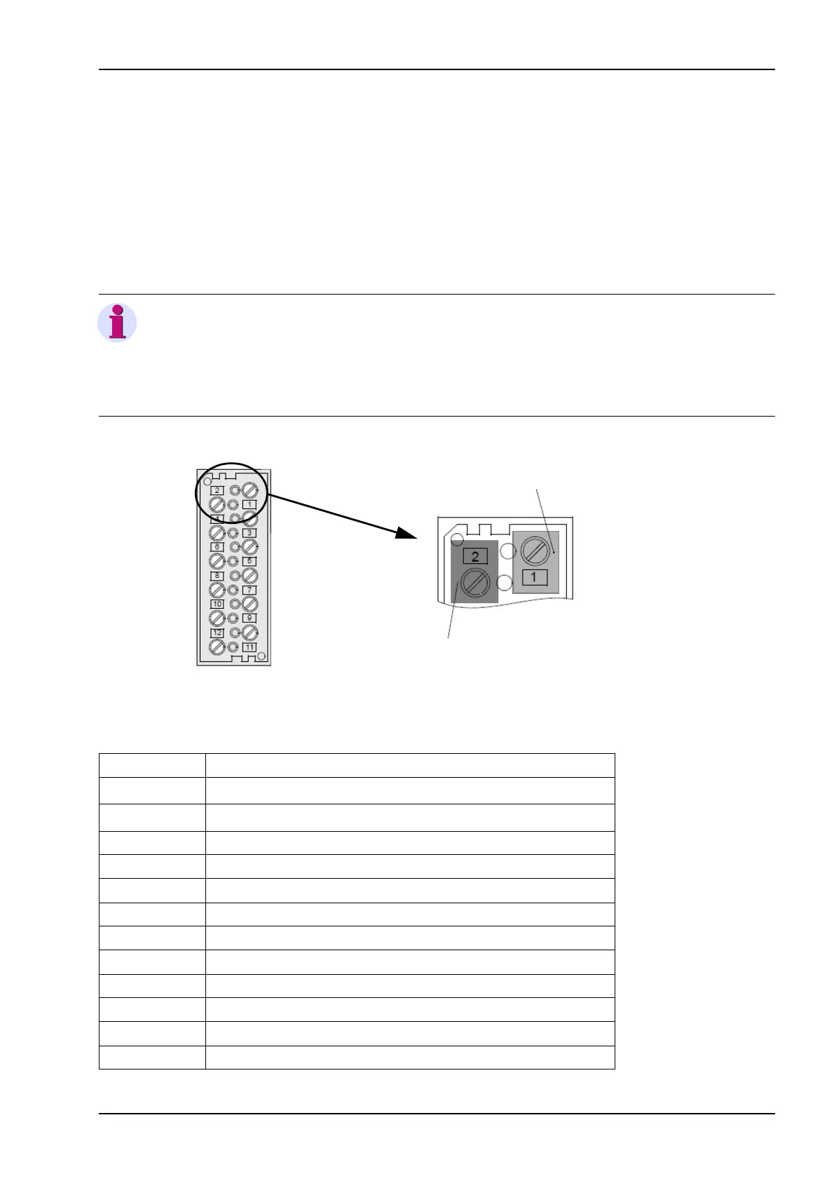
The screw-type terminals on the 12-pin terminal block on the housing are loose on delivery.
Figure 7 Screw-type terminals on the 12-pin terminal block
Table 4 Terminal block
NOTE
For electromagnetic compatibility reasons you must twist the line pair
with about 20 turns between the 7XT33 (clamps 11/12) and the 7XT34
(clamp 1B4), see Figure 10. The line must not be longer than 35 cm in
the twisted condition.
Connector Designation
1 Auxiliary voltage, L1 (U
H+
)
2 Auxiliary voltage, L2 (U
H-
)
3 Auxiliary voltage, L3
4Earth, PE
5 Signal relay L+
6 Blocking input (+)
7 Signal relay, 20-Hz voltage no available
8 Blocking input (-)
9 Signal relay, 20-Hz voltage available
10 reserved
11 20-Hz output, A
12 20-Hz output, B
12-pole
Screw-type terminal 2
Screw-type terminal 1
 Loading...


