Company Confidential s Com
Copyright 2005© Siemens AG
Page 21 of 53
TD_Repair_L2.5_A70_A75_R1.0.pdf Release 1.0
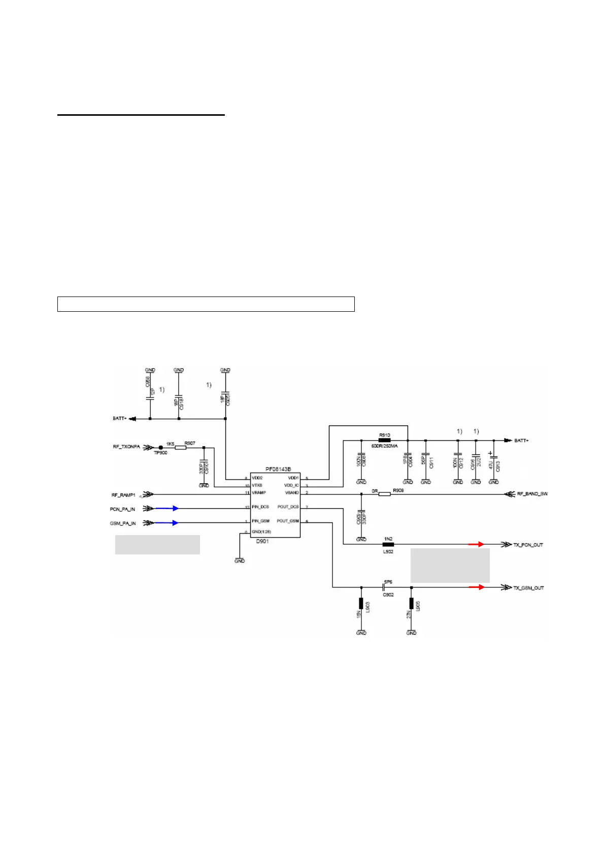
Transmitter: Power Amplifier
The output signals (PCN_PA_IN , and GSM_PA_IN) from the TxVCO are led to the power
amplifier. The power amplifier is a PA-module N901 from Hitachi. It contains two separate 3-
stage amplifier chains GSM850/EGSM900 and GSM1800 / GSM1900 operation. It is
possible to control the output-power of both bands via one VAPC-port. The appropriate
amplifier chain is activated by a logic signal
RF_BAND_SW (TDMA Timer P10) which is provided by
the EGOLDLite.
To ensure that the output power and burst-timing fulfills the GSM-specification, an internal
power control circuitry is use. The power detect circuit consists of a sensing transistor which
operates at the same current as the third RF-transistor. The current is a measure of the
output power of the PA. This signal is square-root converted and converted into a voltage by
means of a simple resistor. It is then compared with the RF_RAMP1
(F12) signal.
The N901 is activated through the signal RF_TXONPA
(TDMA Timer P3).
The required voltage BATT+ is provided by the battery.
Circuit diagram
from TxVCO
to antenna
connecto

 Loading...