INTRODUCTION
_________________________________________________________________________________________________________
1-2
SIG-QG-17-05 DECEMBER 2017
Version No.: A
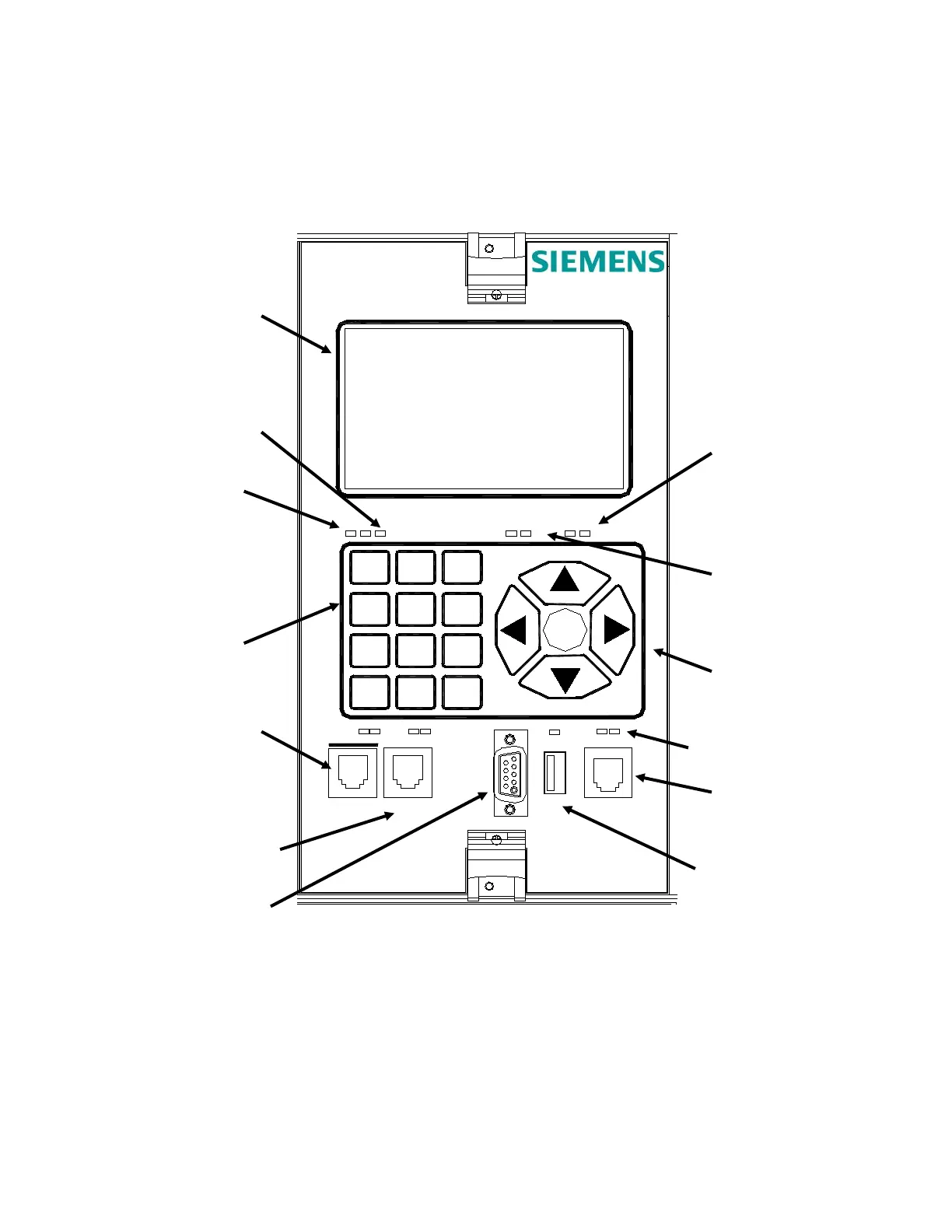
1.1.1 GCP Display Module Controls, Indicators, Connectors, and Display
The GCP Display module controls, indicators, connectors, and display are shown in Figure 1-2
and described in Table 1-1.
Figure 1-2 A80485 GCP Display Module Controls, Indicators, and Display
(M9)
1
Symbol
2
ABC
3
DEF
4
GHI
5
JKL
6
MNO
7
PQRS
8
TUV
9
WXYZ
HELP
0
Space
BACK
ENTER
USB
LAPTOP
DIAG
CPU
SEAR
TX RX
POWER
TX RX
DISPLAY
Module
A80485-2
COM
TX RX
ECHELON
ETHERNET 2ETHERNET 1
ETH
PWR
Powered
Keys
(Unpowered)
TX RX LEDS
LEDS
TX RX LEDS
LEDS
(Diag) Port
 Loading...


