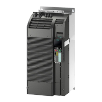
Do you have a question about the Siemens SENTRON ATC6500 and is the answer not in the manual?
Explains the purpose, scope, knowledge required, and target audience of the manual.
Details product certification, reference documents, training, and technical support.
Covers crucial security information and open source software licenses for safe product operation.
Outlines the key functionalities, metering capabilities, and application areas of the ATC6500.
Lists the compatible Siemens air and molded case circuit breakers for use with the ATC6500.
Explains transfer control concepts, including types and specific application scenarios like network/network.
Details how the ATC6500 manages motor-driven circuit breakers, remotely operated equipment, and contactors.
Describes how the ATC6500 performs voltage measurements and the associated parameters for adjustment.
Explains the meaning of various LEDs on the operator panel indicating device and switching device status.
Provides a function description for each key on the ATC6500 operator panel.
Describes the USB front interface for parameterization and its connection requirements.
Explains how to navigate the front-mounted LCD display for parameterization and reading values.
Details the symbols used in the main menu for accessing functions and navigating measurement pages.
Covers essential functions like setting the real-time clock, password protection, and keypad lock mechanisms.
Introduces advanced features such as remote variables, user limits, timers, and counters for flexible configuration.
Specifies the required dimensions for the door cutout for mounting the ATC6500.
Provides a step-by-step procedure for securely mounting the ATC6500 device in the door cutout.
Details the power supply options for the ATC6500, including AC, DC, dual supply, and UPS.
Illustrates various connection diagrams for transfer between sources with different breaker configurations.
Lists required accessories and permissible mechanical interlocking combinations for Siemens circuit breakers.
Provides specific connection diagrams and parameter settings for 3VA molded case circuit breakers.
Offers connection diagrams and parameter settings for 3WL air circuit breakers, including FS I-III variants.
Presents connection diagrams and parameter settings for 3WT8 air circuit breakers.
Explains the four operating modes: OFF, TEST, Manual, and Automatic, and how to set them.
Details the integrated and expandable digital inputs and outputs, their functions, and specifications.
Guides through parameter adjustment using the device's setup menu and navigation keys.
Explains how to modify parameters, restore factory settings, and save changes.
Covers parameterization using PC software via RS485 or Ethernet expansion modules.
Introduces MODBUS protocols (RTU, TCP, ASCII) supported by the ATC6500 via its interfaces.
Details the structure and components of the MODBUS RTU protocol messages.
Explains the available MODBUS functions (Read Input Register, Preset Single Register, etc.) for interacting with the ATC6500.
Provides a comprehensive list of measured values, status bits, commands, and their corresponding MODBUS addresses.
Describes the procedure for reading event log entries from the ATC6500 using MODBUS commands.
Explains how to retrieve device parameters using MODBUS function 04 and 06.
Details the MODBUS procedures for modifying device parameters and saving them.
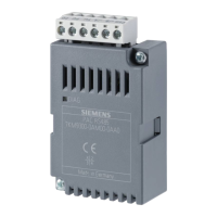
Lists available expansion modules (DI/DO, Ethernet) and their technical specifications for extending ATC6500 functionality.
Describes the IP protective seal for achieving IP65 protection and its mounting.
Explains the USB front interface for parameterization via PC software.
Covers different transfer types, including open transition and IN-PHASE transition, and their characteristics.
Illustrates the defined sequences for applications A, B, C, D, and O, detailing the breaker states during transfer.
Provides essential guidelines and protective measures for handling ESD-sensitive components.
| Category | Control Unit |
|---|---|
| Manufacturer | Siemens |
| Display | LCD |
| Power Supply | 24 V DC |
| Mounting | DIN rail mounting |
| Protection Class | IP20 |
| Measuring Category | CAT III |
| Operating Temperature | -10°C to +55°C |
| Relative Humidity | 5% to 95% non-condensing |
| Communication Interfaces | Ethernet |
| Protocol | Modbus RTU |
