Operation
8.2 Inputs and outputs of the ATC6500
3KC ATC6500 transfer control device
152 Manual, 05/2019, L1V30538268002A-01
The following functions are stored as factory defaults for the inputs:
Open Source 1 contactor/breaker
OUT2 56-57 Close Source 1 contactor/breaker
Open Source 2 contactor/breaker
Close Source 1 contactor/breaker
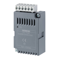
8.2.6 Addressing the expansion modules with digital inputs/outputs
If only one expansion module with digital inputs is installed in the ATC6500 it is designated
INP9, 10 ... regardless of whether it is inserted in slot 1 or 2.
If there are 3 modules with inputs in the ATC6500, the module in slot 1 is addressed as
INP9, 10 ..., the module in slot 2 as INP11, 12 ... and the module in slot 3 as INP13, 14. The
addressing for outputs follows the same pattern.
Note
Expansion module removed
If there are 2 modules in the device and the module in slot
1 is subsequently removed, then
the addressing of the remaining module in slot 2 changes from INP11,12 to INP9, 10. The
device will indicate this change at the necessary restart (see chapter
Behavior of the
ATC6500 after inserting a module
(Page 59)).
8.2.7 Integrated RS485 interface COM1
An RS485 interface COM1 is located on the ATC6500:
Recommended cable cross-section
RS485 interface
0.2 - 2.5 mm
2
(24 - 12 AWG)
acc. to UL508:
0.75 - 2.5 mm
2
(18 - 12 AWG)
Connect all RS485 interfaces in parallel to an interface converter using a twisted pair cable.
Check for the correct polarity (terminals A and B). The interface converter must be insulated
and have an automatic enabling cable control circuit. If you have connected several devices,
use the keypad to set up the functions on each device and assign a unique address for
communication via RS485 to each ATC, starting with 01. Ensure that the data transmission
rate and parity of the computer match the settings for RS485 in the controllers.
 Loading...
