Connection
7.4 Connection of 3VA molded case circuit breakers
3KC ATC6500 transfer control device
Manual, 05/2019, L1V30538268002A-01
117
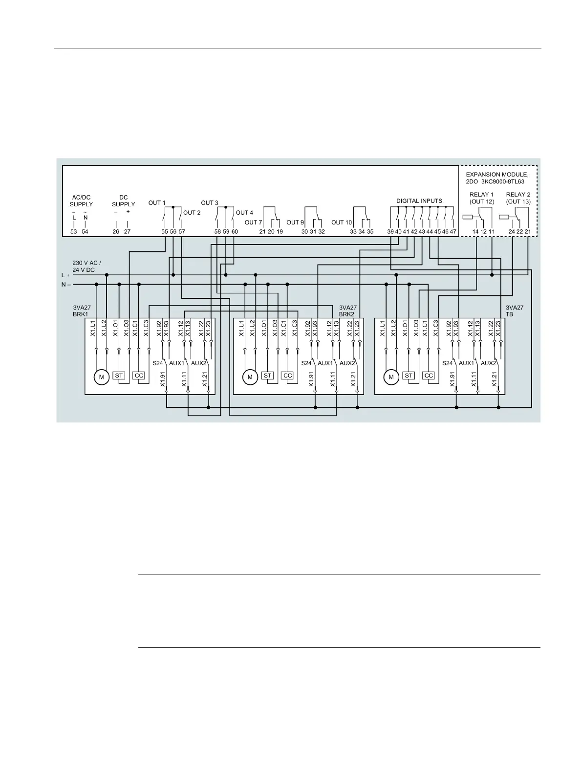
7.4.2.2 Transfer between three 3VA27 molded case circuit breakers, with electrical interlock
The following diagram applies for the applications 2S-1T-PL and 2S-NPL:
You can find more information on the applications in chapter Load management with the
ATC6500 (Page 20)
3VA molded case circuit breaker for Source 1
3VA molded case circuit breaker for Source 2
3VA molded case circuit breaker as tie breaker
Auxiliary switch (for electrical interlocking)
Auxiliary switch (status)
Alarm auxiliary switch (trip)
Note
IEC regulations
According
to IEC regulations, the fusible element must be connected via a cable compliant
61439-1 which is protected against ground faults and short circuits. To this end,
please observe the applicable national standards for electrical installatio
ns.

 Loading...


