v
SIG-QG-17-05 DECEMBER 2017
Version No.: A
3.2 USB OPERATION ....................................................................................................................... 3-2
3.2.1 USB Drive File Structure.............................................................................................. 3-2
3.2.2 USB Menu ................................................................................................................... 3-3
3.2.3 USB Detection ............................................................................................................. 3-3
3.2.4 USB Menu ................................................................................................................... 3-4
3.3 MODULE SOFTWARE UPDATES .............................................................................................. 3-5
3.4 DISPLAY MODULE POWERED ETHERNET PORT .................................................................. 3-5
3.4.1 Display Module to Ethernet 1 Port Power-Over-Ethernet (POE) Device Connection 3-6
3.5 ETHERNET NETWORK CONNECTION .................................................................................... 3-7
List of Figures
Section Title Page
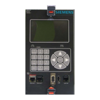
Figure 1-1 A80485 Siemens Display Module........................................................................................... 1-1
Figure 1-2 A80485 GCP Display Module Controls, Indicators, and Display ............................................ 1-2
Figure 2-1 GCP4000 and GCP5000 Main Screens ................................................................................. 2-1
Figure 2-2 GCP3000+ Main Screens ....................................................................................................... 2-1
Figure 2-3 Keypad, and Navigation Cluster Keys .................................................................................... 2-2
Figure 2-4 Keypad Operation ................................................................................................................... 2-2
Figure 2-5 Navigation Key Cluster ........................................................................................................... 2-2
Figure 3-1 Display Module to Laptop Connection .................................................................................... 3-1
Figure 3-2 Inserting a USB Drive ............................................................................................................. 3-3
Figure 3-3 USB Detected Screen ............................................................................................................ 3-3
Figure 3-4 USB Menu Screens GCP4000 and GCP5000 ....................................................................... 3-4
Figure 3-5 USB Menu Screens GCP3000+ ............................................................................................. 3-4
Figure 3-6 Display Module to GCP Module Serial Cable Connection ..................................................... 3-5
Figure 3-7 Display Module to Ethernet Power-Over-Ethernet Device Connection .................................. 3-6
Figure 3-8 Display Module to Ethernet Network Connection ................................................................... 3-7
List of Tables
Section Title Page
Table 1-1 Display Module Controls, Indicators, Connectors, and Display Descriptions .......................... 1-3
Table 1-2 Resource Documents .............................................................................................................. 1-4
 Loading...


