Siemens LV 10 · 2004
7/4
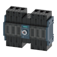
SENTRIC Switch Disconnectors
General data
SENTRIC LD Main Control and EMERGENCY STOP Switches from 16 A to 125 A
7
■
Technical specifications
1) With appropriate operating mechanisms according to DIN VDE 0113 (see
selection and ordering data).
Standards DIN VDE 0660, IEC 60947
Switch Type
3LD2 0 3LD2 1 3LD2 2 3LD2 5 3LD2 7 3LD2 8
Number of contacts 3/4 3/4 3/4 3/4 3/4 3/4
Rated insulation voltage
U
i
Rated operating voltage
U
e
Rated frequency
Rated impulse withstand voltage
U
imp
V
AC V
Hz
kV
690
690
50 ... 60
6
690
690
50 ... 60
6
690
690
50 ... 60
6
690
690
50 ... 60
6
690
690
50 ... 60
6
690
690
50 ... 60
6
Rated short-time withstand current (1 s current, rms value)
Short-circuit protection, max. back-up fuse (gL)
A
A
340
20
640
25
640
50
1260
63
2000
100
2000
125
Rated uninterrupted current I
u
A 16 25 32 63 100 125
AC-21A load-break switch Rated operating current I
e
A 16 25 32 63 100 125
AC-3 motor load switch
in-service switching
of individual motors
Rating
at 220 V ... 240 V
at 380 V ... 440 V
at 660 V/690 V
kW
kW
kW
3.0
5.5
5.5
4.0
7.5
7.5
5.5
9.5
9.5
11.0
18.5
15.0
18.5
30.0
22.0
22.0
37.0
30.0
AC-23A main control switch
Maintenance switch
frequent, but not
in-service switching
of individual motors
Rating
at 220 V ... 240 V
at 380 V ... 440 V
at 660 V/690 V
kW
kW
kW
4.0
7.5
7.5
5.0
9.5
9.5
6.0
11.5
11.5
11.0
22.0
18.5
18.5
37.0
30.0
22.0
45.0
37.0
Power loss per conducting path at I
e
W 0.5 1.1 1.8 4.5 7.5 12
Touch protection to DIN VDE 0106 Part 100 yes yes yes yes yes yes
Mechanical endurance Oper-
ating
cycles
100 000 100 000 100 000 100 000 100 000 100 000
Operating frequency 1/h
50 50 50 50 50 50
Permissible ambient temperature °C
–25 ... +55 –25 ... +55 –25 ... +55 –25 ... +55 –25 ... +55 –25 ... +55
Isolating characteristics up to ...
V
690 690 690 690 690 690
Main control and EMERGENCY-STOP switch characteristics
1)
yes yes yes yes yes yes
Conductor cross-sections for main conductors
Connection type
mm
2
Clamp connections
solid or stranded 1 ... 6 1.5 ... 16 1.5 ... 16 2.5 ... 35 4 ... 50 4 ... 50
flexible with end sleeve (max.) mm
2
4 10 10 16 35 35
Auxiliary switches
Rated insulation voltage
U
i
V 500 500 500 500 500 500
Rated operating voltage U
e
AC V 500 500 500 500 500 500
Rated uninterrupted current I
u
A 10 10 10 10 10 10
Rated operating current I
e
AC-15 at 120 V A 6 6 6 6 6 6
at 220 V ... 240 V A
3 3 3 3 3 3
at 380 V ... 415 V A
1.8 1.8 1.8 1.8 1.8 1.8
at 500 V A
1.4 1.4 1.4 1.4 1.4 1.4
Short-circuit protection, auxiliary switch, max. back-up fuse (gL/gG) A
10 10 10 10 10 10
Conductor cross-section for auxiliary conductors
Connection type Clamp connections
solid or stranded mm
2
2 ×
(0.75 ... 2.5)
1 ×
(0.75 ... 4)
1 ×
(0.75 ... 4)
1 ×
(0.75 ... 4)
1 ×
(0.75 ... 4)
1 ×
(0.75 ... 4)
Finely stranded with end sleeve mm
2
2 ×
(0.75 ... 2.5)
1 ×
(0.75 ... 2.5)
1 ×
(0.75 ... 2.5)
1 ×
(0.75 ... 2.5)
1 ×
(0.75 ... 2.5)
1 ×
(0.75 ... 2.5)
Standards UL/CSA
Switch Type
3LD2 0 3LD2 1 3LD2 2 3LD2 5 3LD2 7 3LD2 8
Rated operating voltage
U
e
AC V 600 600 600 600 600 600
Rated uninterrupted current I
u
A 10 20 30 60 100 125
Current rating
600 A 600 A 600 A – – –
Pilot duty
P600 P600 P600
Conventional thermal current I
th
A 16 25 32 63 100 125
Max. rating (AC-3) 3 ∼ 120 V HP
1 – – – – –
AC motors 40 Hz ... 60 Hz 240 V HP
3 7.5 10 15 30 40
(HP = PS) 480 V HP
7.5 10 20 40 60 75
600 V HP
10 15 30 50 75 100
1 ∼ 120 V HP
0.5 2 2 – – –
240 V HP
1.5 3 3 10 – –
Conductor cross-sections copper cable AWG
18 ... 10 14 ... 8 14 ... 8 14 ... 6 12 ... 1 12 ... 1
Tightening torque Nm
1.5 ... 2 2 ... 2.5 2 ... 2.5 2.5 ... 3 2.5 ... 3 2.5 ... 3