5 / 10
Siemens Electromotoric actuators for valves A6V10628469_de--_c
Building Technologies 2018-03-12
Technical Data
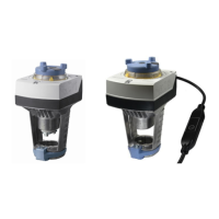
SAY..P
Power supply Operating voltage
SAY31P03 AC 230 V ±15%
SAY61P03 AC 24 V ± 20% / DC 24 V + 20% / -15%(SELV)
SAY81P03 AC 24 V ±20% / DC 24 V + 20 % / -15%(SELV)
Frequency 45…65Hz
External supply line protection (EU)
∂ Fuse slow 6…10 A
∂ Circuit breaker max. 13 A, Characteristic B, C,
D according to EN 60898
∂ Power source with current limitation of
max. 10 A
Power consumption at 50 Hz
SAY31P03 Stem retracts / extends 6 VA / 3.5 W
SAY61P03 Stem retracts / extends 8 VA / 3.75 W
SAY81P03 Stem retracts / extends 5 VA / 3.75 W
Function data Positioning times (with the specified nominal stroke)
The positioning time can vary, depending on the type
of valve -> refer chapter "Type summary" (page 2)
SAY31P03, SAY61P03, SAY81P03 30 s
Positioning force 200 N
Nominal stroke 15 mm
Permissible medium temperature (valve fitted) 1…120 °C
Signal inputs Positioning signal ”Y” SAY31P03, SAY81P03 3-position
SAY31P.. Voltage AC 230 V ±15%
SAY81P.. Voltage AC 24 V ± 20 % / DC 24 V + 20 % / -15%
SAY61P03 (DC 0...10 V) Current draw ≤ 0.1 mA
Input impedance ≥ 100 kΩ
SAY61P03 (DC 4...20 mA) Current draw DC 4...20 mA ± 1%
Input impedance ≤ 500 Ω
Parallel operation SAY61P03 ≤ 10 (depending on controler output)
Forced control Positioning signal ”Z” SAY61P03 R = 0…1000 Ω, G, G0
R = 0…1000 Ω Stroke proportional to R
Z connected to G Max. stroke 100%
Z connected to G0 Min. stroke 0%
Voltage Max. AC 24 V ± 20%
Max. DC 24 V + 20% / -15%
Current draw ≤ 0.1 mA
Position feedback Position feedback U SAY61P03 DC 0...10 V
Load impedance > 10 kΩ res.
Load Max. 1 mA
Connecting cable Wire cross-sectional areas
0.75…1.5 mm
, AWG 20…16
Cable entries SAY..P..
EU: 2 entries ⊕ 20.5 mm (for M20)
1 entry ⊕ 25.5 mm (for M25)
1)
Observe acting direction of DIL switches
2)
AWG = American wire gauge

 Loading...