Connections and LEDs
10
Siemens AB
Security Products 05.2015
7.2 Port locations
Port name Description
DC POWER INPUT DC power input (12 V DC or 24 V DC)
FLN RS485 RS-485 bus for AC5100, FLN bus
READER 1-8 Card reader: communication, power, LED’s
RELAY 1-8 OUT Door lock / strike relay driven output
D/C 1-8 Door contact
REX 1-8 Request to exit input (REX)
IN 1-16 Inputs
AUX 1-8 Open-collector 12 V DC outputs
FOR
1-2 IN
FOR inputs (e.g. fire alarm button)
FOR
1-2 OUT
FOR outputs
LOCAL IN Tamper input for local tamper detection
LOCAL OUT Alarm output (e. g. siren, strobe light)
SRB RS485 Connection for a serial card reader
SRB PWR Power output for serial card readers
7.3 Reader wiring
Wiegand reader wiring
Reader Type D0 D1 GRN RED 0 V 12 V
Wiegand D0 D1 GRN RED 0 V 12 V
RS-485 reader wiring
Reader Type S - + 12 V 0 V
RS-485 Shield - or B
+ or A
8V/12V 0V/GND
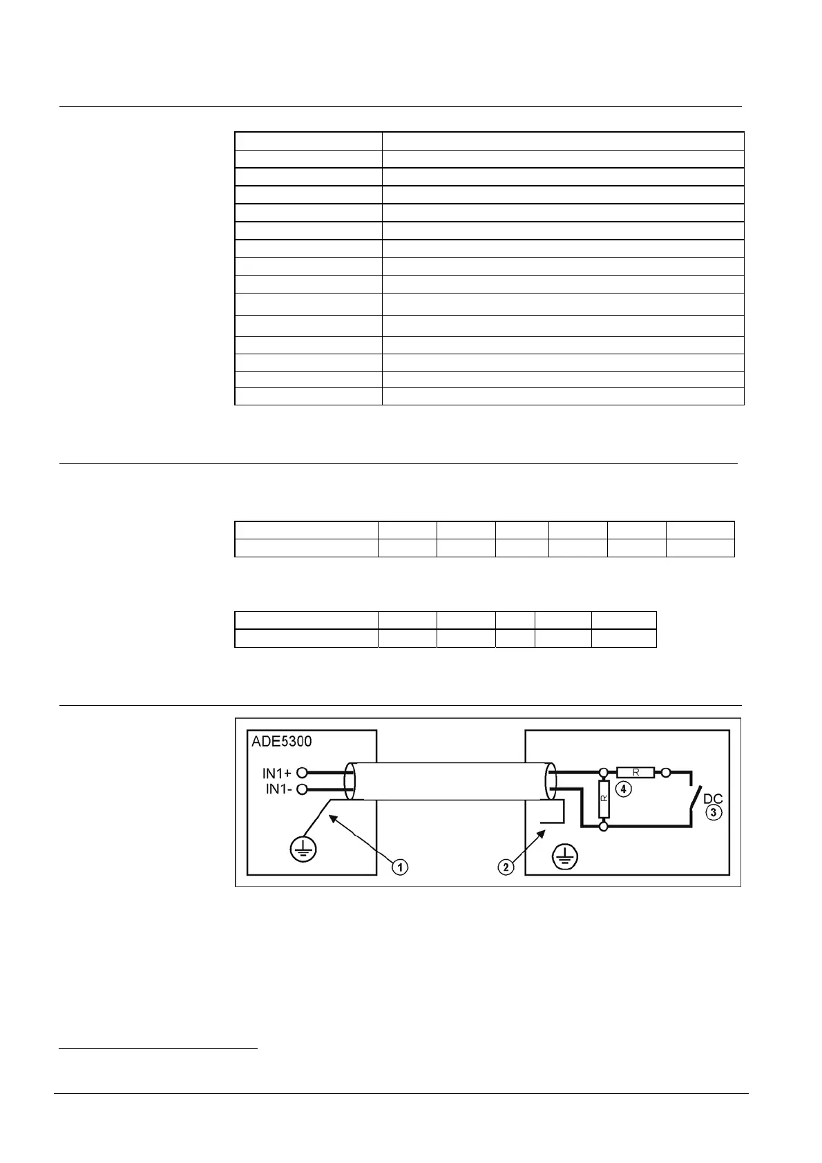
7.4 Wiring of monitored input
1 Connect the shielding to the housing earth.
2 Insulate the shielding at the input (e.g. door contact), do not connect it.
3 DC: door contact
4 R: terminating resistors each 22 kOhm
Fig. 2 Wiring of monitored input
FOR: Fire Override
 Loading...