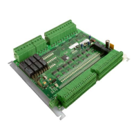
Connections and LEDs
13
Siemens AB
Security Products 05.2015
LK29 No Link
– FOR inactive: Corresponding relays not energized
– FOR active: Corresponding relays that are energized (door released by time schedule for example) will be de-
energized.
Link Set
– FOR inactive: Corresponding relays energized
– FOR active: Corresponding relays that are de-energized (door released by time schedule for example) will be
energized.
7.7 LEDs
LED Description
ACT ACTIVITY LED
1. LED blinking quickly: Firmware needs to be downloaded
2. LED blinking slowly (approx. once per sec): Firmware has been downloaded
FLN COM The LED flashes when the ADE5300 is sending data to the AC5100.
SRB COM The LED flashes when the ADE5300 is receiving data from an RS485 card
reader.
RLY (1-8) The Output relays status is displayed as activated with green LEDs.
IN1 – IN32
REX1 – REX8
DC1 – DC8
FOR1 IN - FOR2 IN
Status of inputs
LED red: Alarm (Fire Override at FOR input)
LED green: Normal
LED orange: Tampering
LED off (only FOR1/2 IN): FOR disabled
ERROR LED active: corrupt or non fully programmable EPROM
PWR LED active: power is applied to the PCB

 Loading...