Standard I/O Modules
76 Unrestricted SICAM A8000 Series, SICAM I/O Modules
DC8-012-2.06, Edition 09.2019
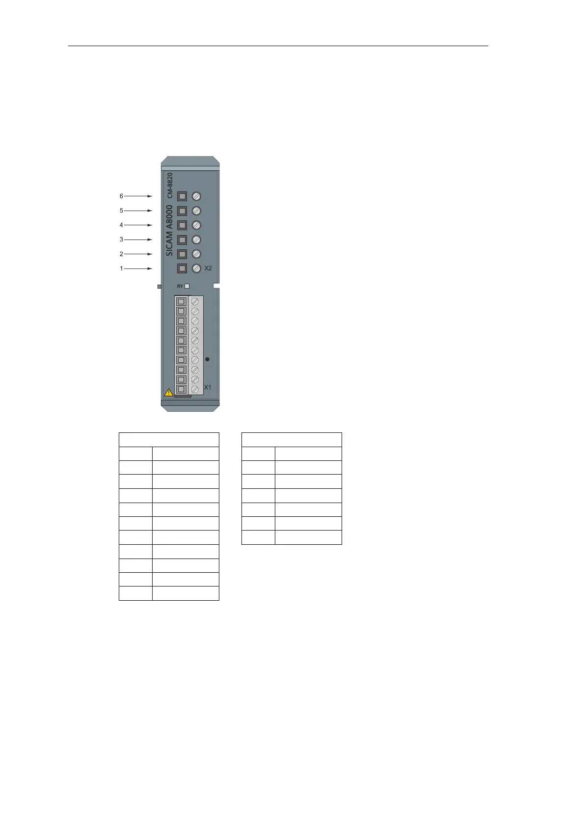
2.10.4 Pin Assignment and Display
The process signals must be connected to screw terminals. The pin assignment of the
peripheral connectors is described in the following table.
X1 X2
Pin Signal Pin Signal
10 DNC 6 I1_P
9 DNC 5 I1_N
8 I1+ 4 I2_P
7 I1- 3 I2_N
6 I2+/IN+ 2 I3_P
5 I2-/IN- 1 I3_N
4 I3+
3 I3-
2 DNC
1 FE shield
I1+/-…I3+/- measuring current outputs
IN+/- (sensitive) ground current
I1_P/N…I3_P/N current transformer inputs
FE functional earth
DNC do not connect
 Loading...