Siemens AG SPR2-310.812.03.01.02 ARCADIS Varic/Orbic
09.06 CS PS SP
Mechanical installation and wiring 13
Page 13 of 20
Medical Solutions
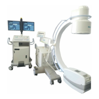
Fig. 8: D31 holder and board, installation location
• Insert the threaded ends of the three spacer bolts from above into the holes in the frame
of the basic unit. The spacer bolts are visible in (Fig.8/p.13) underneath the mount-
ing plate..
• Screw down the three spacer bolts from the underside of the basic unit's frame with
three nuts, washers, and lock washers.
• Attach the 4 circuit board holders to the mounting plate with 4 screws, 4 washers, and
retaining rings. See (Fig.7/p.12).
• Clip the D31 board onto the circuit board holders. Make sure the board clicks in all the
way in the circuit board holders.
Wiring for systems without the 3D reconstruction option installed 0
Removing the wire from the M16.K1.3 and M16.K1.4 relays to D1.X14
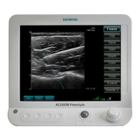
Fig. 9: M16.K1 relay location
• At the M16.K1 relay (emergency stop relay, see (Fig.9/p.13)) remove the M16.K1.3
and M16.K1.4 wires.
• On the D1 board, detach the D1.X14 plug.
• Remove the wire. To do so, cut open the appropriate cable ties.
¹ The wire will be replaced with the Y cable included in the accessory kit.

 Loading...