Removing the ON/OFF Assembly 2 - 3
Siemens AG n.a. SP00-000.841.01 Page 3 of 4 ARCADIS
Medical Solutions Rev. 01 08.05 CS PS 24 System Manual
Removing the ON/OFF assembly 2
• The ON/OFF assembly is attached to the base plate with 4 Allen screws.
Loosen the 4 Allen screws.
• Pull the ON/OFF assembly approx. 10 cm out of the monitor trolley (Fig. 4).
• Pull out connectors D50.X6, D50.X7, D50.X8, D50.X9.
• Disconnect the cables connected to terminal strips D50.X2, D50.X3, D50.X4 and
D50.X11 of the ON/OFF assembly.
• Disconnect cables D66.X5 and D66.X1 from the PC and pull them back to the ON/OFF
assembly. To do this, cut open the existing cable ties.
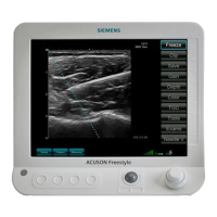
• If the 3D Reconstruction option is present, disconnect the CAN cable from the
USB-to-CAN converter (1/Fig. 6) and pull it back to the ON/OFF assembly.
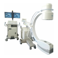
• Unscrew the ground wire from the ON/OFF assembly (1/Fig. 5).
• Unscrew the cable clamps of the monitor trolley cable and the power cable (2 & 3/Fig. 5).
• Disconnect the power cable (ground wire, N and L1) from terminal strip 1/Fig. 4.
• Pull the power cable and the monitor trolley cable out of the ON/OFF assembly.
• The ON/OFF assembly can now be taken out of the monitor trolley. Due to the weight of
the assembly, 2 persons are needed for lifting it.
Fig. 5 Fig. 6

 Loading...