7SR11 & 7SR12 Description Of Operation
©2012 Siemens Protection Devices Limited Chapter 1 Page 16 of 76
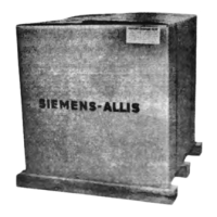
Figure 1-11 Relay shown withdrawn
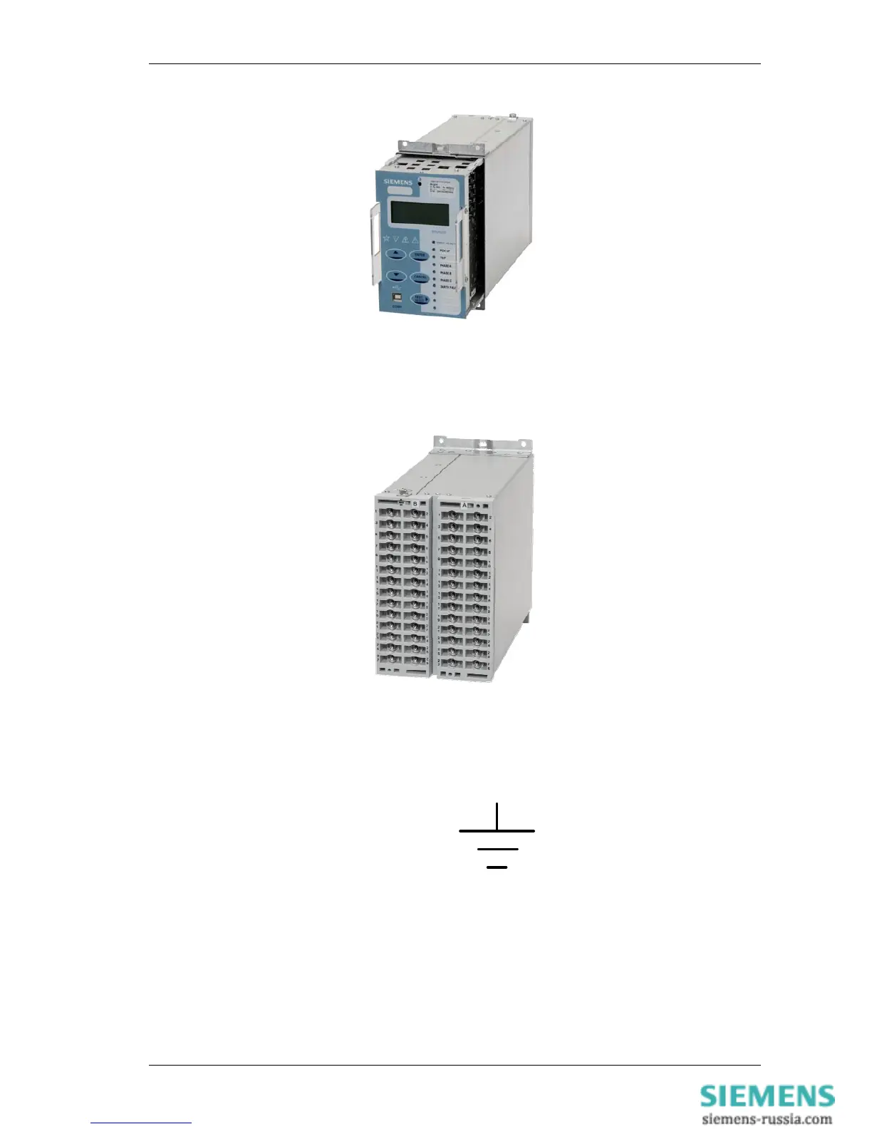
The rear terminal blocks comprise M4 female terminals for wire connections. Each terminal can accept two 4mm
crimps.
Figure 1-12 7SR11 Rear view of 7SR11 Relay
Located at the top rear of the case is a screw clamp earthing point, this must be connected to terminal 28 and
directly to the main panel earth. This connection point is indicated by the following symbol.
Figure 1-13 Earth connection Symbol
2.3 Front Cover
As standard the relay is supplied with a transparent front cover. The front cover is used to secure the relay
assembly in the case.
 Loading...