V1.0 Page 21 of 46 ICM MP CCQ ST
C45, M50 AND MT50 Company Confidential © Copyright Siemens AG 05/02
4.5.2 Transmitter: Power Amplifier
The output signal (PCN_PA_IN) from the TX-VCO are led to the power amplifier
(Z900) passing a matching circuit. The PA is a “two in one” PA (GSM part not used)
and, is connected directly to Batt+.
After amplification, a part of the output signal (TX_PCN_OUT) is decoupled via a
directional coupler. The other part runs through the antenna switch (Z880) and the
antenna connector (X870) to the Antenna. The decoupled part is equalised by the
detector diode (V920) and used from the (N920) to get a PA control voltage by
comparing this voltage with the PA_RAMP signal provided from the
EGOLD+ (GAIM/BASEBAND H2).
The (N920) is activated through the signal TXONPA and TXON1.
The required voltage BATT+ is provided by the battery.
The required voltage VCC2_8 is provided by N840.
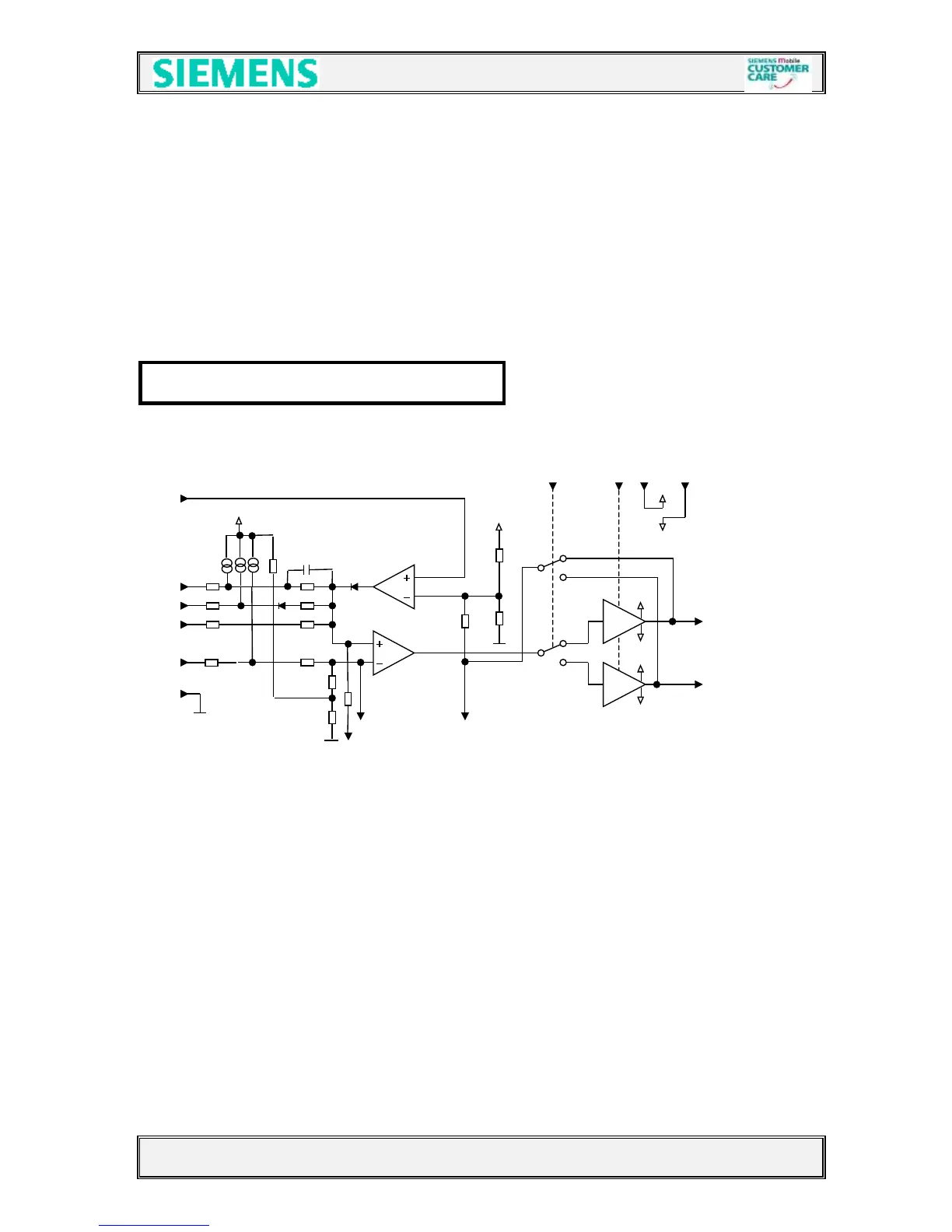
Blockdiagram of LML361 (PA control IC9
Vdd