Do you have a question about the Siemens CALOMAT 6 and is the answer not in the manual?
Lists available CALOMAT 6 analyzer types and their order numbers.
Explains the document's scope and target audience for safety information.
Identifies other manuals necessary for comprehensive understanding of the CALOMAT 6.
Tracks revisions and updates made to the SIL Safety Manual over time.
Provides disclaimers and directs users to external resources for additional details.
Defines a safety-instrumented system (SIS) and its core components.
Describes the operating principle and key functional characteristics of the CALOMAT 6.
Explains Safety Integrity Levels (SIL) according to IEC 61508 and factors determining SIL.
Details the CALOMAT 6's intended use in safety applications and its compliance with standards.
Defines the specific safety function of the CALOMAT 6 and its potential dangerous failure mode.
Specifies crucial parameter settings required for the CALOMAT 6's safety function.
Guides users on handling device faults, repairs, and obtaining support.
Recommends procedures for regular maintenance and functional checks of the CALOMAT 6.
Lists the essential conditions and characteristics for the safe operation of the CALOMAT 6.
Presents the official declaration of the CALOMAT 6's compliance with SIL standards.
Summarizes the hardware assessment findings, including FMEDA and failure rate analysis.
Provides a glossary of abbreviations and their full meanings used throughout the manual.
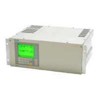
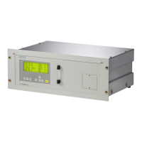
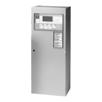
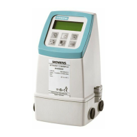
The CALOMAT 6 is a thermal conductivity gas analyzer designed for continuous gas analysis, particularly for use in safety-instrumented systems (SIS). It is available in various types, including CALOMAT 6F (7MB2511, 7MB2517) and CALOMAT 6E (7MB2521, 7MB2527). This device is a component of a safety-instrumented system, which typically comprises a sensor (the analyzer), a logic unit/control system (e.g., a PLC), and a final controlling element (e.g., a valve). The CALOMAT 6 contributes to safety functions by monitoring gas concentrations and providing an analog output that can be used by a logic solver to maintain a safe system status.
The CALOMAT 6 operates based on the principle of different thermal conductivities of gases. It utilizes a micro-mechanically manufactured Si chip with a measuring diaphragm containing thin-film resistors. These resistors are maintained at a constant temperature. The current required to achieve this constant temperature varies depending on the thermal conductivity of the sample gas. This raw value is then electronically processed to calculate the gas concentration. To ensure measurement accuracy and stability, the sensor is housed in a thermostatically-controlled stainless steel enclosure to suppress ambient temperature influences. Additionally, the sensor is designed for indirect flow to prevent flow-related disturbances.
The primary safety function of the CALOMAT 6 is user-defined threshold monitoring. For safety applications, only the isolated analog output, set to 4-20 mA (NAMUR), is considered. A dangerous failure is defined as a deviation of the output current of ±5% full span. The device is suitable for monitoring limits in safety applications and meets the functional safety requirements of SIL 1 in accordance with IEC 61508 or IEC 61511-1. The relay output is exclusively used for diagnostics in safety-instrumented systems.
The CALOMAT 6 hardware provides failure data compliant with IEC 61508 / IEC 61511. The hardware assessment does not include an assessment of the software. Key safety characteristics for the CALOMAT 6, as per the SIL Declaration of Conformity, include:
These characteristics are valid under specific conditions: low demand mode operation, safety-related parameters entered and checked before operation, blocking against unauthorized changes, an average long-term temperature of 40°C, compatibility of all materials with process conditions, and an MTTR of 8 hours. The useful life of the Gas Analyzer CALOMAT 6 is estimated to be 10 years.
The CALOMAT 6 is primarily used for monitoring the concentration of hydrogen and noble gases. It offers an accuracy of ±5% of full span for its safety-instrumented function. The device is designed to be integrated into safety-instrumented systems where its analog output feeds into a logic solver (e.g., a PLC) that processes the measurement for safety-critical actions. The device's settings, particularly the analog output function (Function Number 70) to "Select 4..20 mA (Namur)," are crucial for its safety function. After configuration, access codes (Function Number 79) should be changed to protect against unauthorized modifications.
Regular maintenance and checking are essential to ensure the CALOMAT 6 continues to fulfill its safety function. It is recommended to check the device's functioning at regular intervals, ideally once a year. This involves testing the basic functionality as described in the instruction manual.
Proof Tests: To detect dangerous undetected faults in the CALOMAT 6 analog output, two proof tests must be performed:
Proof Test 1:
Proof Test 2:
These proof tests are designed to detect more than 90% of possible "du" (dangerous undetected) failures in the CALOMAT 6. The testing intervals are determined by the PFDAVG of the individual safety circuit, with a recommended maximum interval of one year, and a recommended proof test interval of once per month.
In case of faults, the procedure described in the device operating manual should be followed. Defective devices should be sent to the Repair Department with details of the fault and the serial number for replacement.
| Brand | Siemens |
|---|---|
| Model | CALOMAT 6 |
| Category | Measuring Instruments |
| Language | English |