4
Smart Infrastructure A6V13605540_en--_b
Smart Infrastructure 2022-10-14
Optional hardware (not provided)
The optional hardware depends on the connection type.
● Bus connection cable: 2 wires, 24 AWG, minimum section: 0.22 mm
2
+ braid
● Power supply cable: 2 wires (red, black), 22 AWG or 0.35 mm
2
● Ethernet cables
● Ethernet switch
● Echelon U60 FT DIN USB Gateway (for LON FT10)
● Double-sided high performance adhesive tape
● LoRaWAN network tester (e.g. Adeunis ARF8123AA)
● High-gain external GSM antenna (e.g. Siretta Oscar 40)
● High-gain external LoRaWAN antenna (e.g. EAD WMO86916)
● Technical documentation of equipment
● Technical documentation of IoT sensors
● Diagram of the communication network(s) of the BMS
The optional hardware cannot be ordered through Siemens.
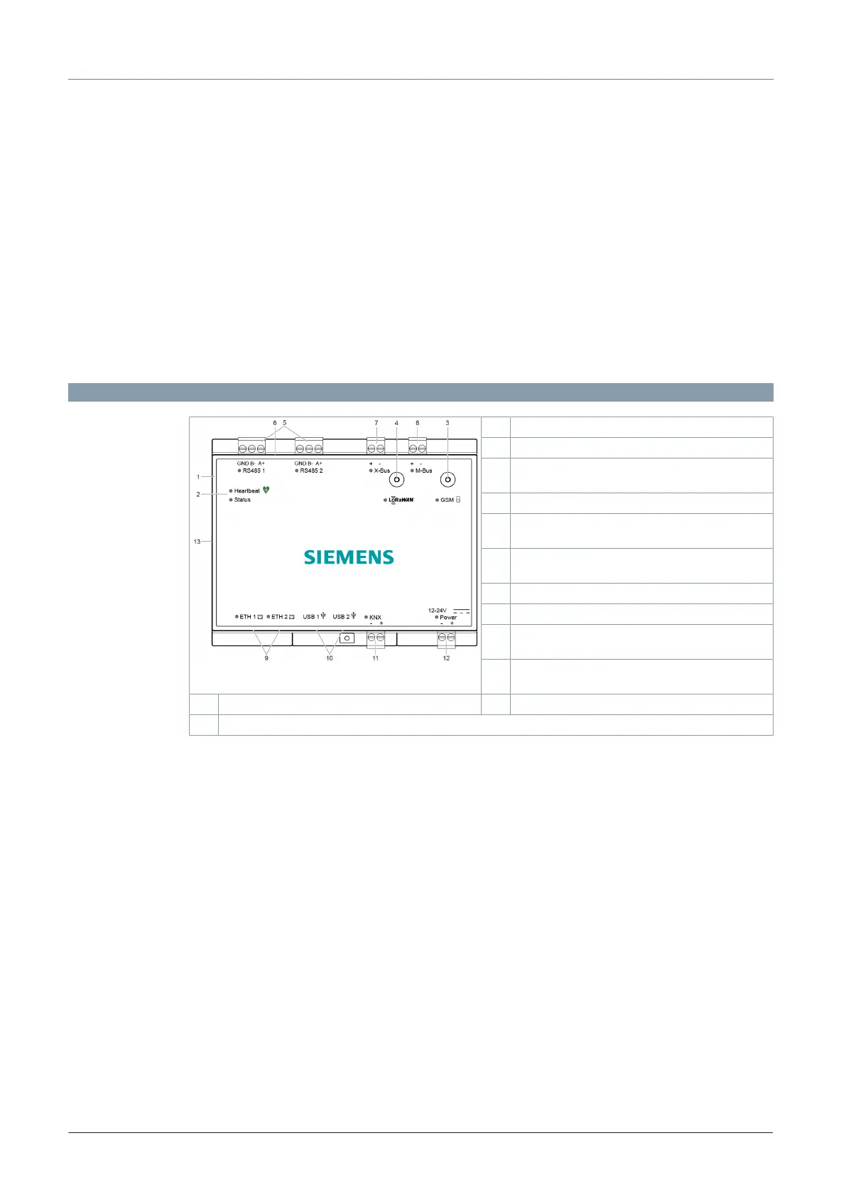
Technical and mechanical design
3 GSM antenna
4 LoRaWAN antenna
5 Plug-in terminal block with screw terminals
RS485 1 / RS485 2 (Modbus RTU)
6 USB micro port (used for maintenance only)
7 Plug-in terminal block with screw terminals
X-bus (LPB-bus)
8 Plug-in terminal block with screw terminals
M-bus
9 Ethernet port 1 and 2
10 USB port 1 and 2
11 Plug-in terminal block with screw terminals
KNX
12 Plug-in terminal block with screw terminals
Power supply
1 Plastic housing 13 Notch for mounting on DIN rails
2 Heartbeat and status LEDs