Do you have a question about the Siemens 181 and is the answer not in the manual?
Explains the safety alert symbol system and graded danger notices.
Defines qualified personnel for operating Siemens products.
Outlines requirements for safe and proper use of Siemens products.
Lists registered and other trademarks.
States the publisher's review and guarantee for the publication's consistency.
Explains the manual's role complementing system manuals for commissioning.
Mentions observing specific notes and symbols used in the documentation.
Discusses Siemens' approach to industrial security and product updates.
Introduces the modular documentation for SIMATIC products.
Lists additional documentation relevant to the specific analog input module.
Provides information on accessing all SIMATIC manuals online.
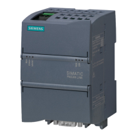
Details the article number and provides a view of the module.
Lists accessories that must be ordered separately for the module.
Shows the terminal assignments for the analog input module.
Presents the internal schematic circuit diagram of the module.
Details configurable measurement types and their associated ranges and coefficients.
Lists and explains the configurable parameters for the analog input module.
Provides detailed explanations for various module parameters.
Explains the function and value ranges for scalable measuring ranges.
Illustrates the assignment of the address space with value status.
Describes the LED displays for module status and errors.
Details the hardware interrupts generated by the module and their OB start information.
Lists diagnostics alarms, their meanings, and remedies.
Presents detailed technical data for the analog input module.
Explains parameter dependencies when using GSD files for configuration.
Describes how to assign parameters and the structure of data records.
Explains the function and control of the switchable wire break check.
Shows digitized representation of bipolar and unipolar input ranges.
Lists decimal/hex values for voltage measuring ranges.
Lists decimal/hex values for resistance-type sensor ranges.
Lists decimal/hex values for thermal resistors.
Lists decimal/hex values for thermocouples.
| Brand | Siemens |
|---|---|
| Model | 181 |
| Category | Network Hardware |
| Language | English |

