Description of the device
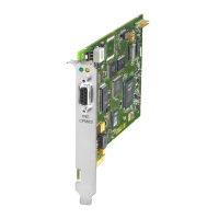
1.2 PROFIBUS interface
CP 5711
Operating Instructions, 02/2018, C79000-G8976-C283-05
11
PROFIBUS interface
PROFIBUS network
The physical link between the PROFIBUS interface and the PROFIBUS network is via a
floating RS-485 interface that is part of the module. Depending on the network configuration,
data rates of 9.6 Kbps up to a maximum of 12 Mbps are possible in the PROFIBUS network.
Note
You will find information about the structure of a PROFIBUS network in the system manual
"PROFIBUS Network Manual". The document is part of the Manual Collection. You will also
find this on the Produc
t Support pages under the following entry ID:
https://support.industry.siemens.com/cs/ww/en/view/35222591)
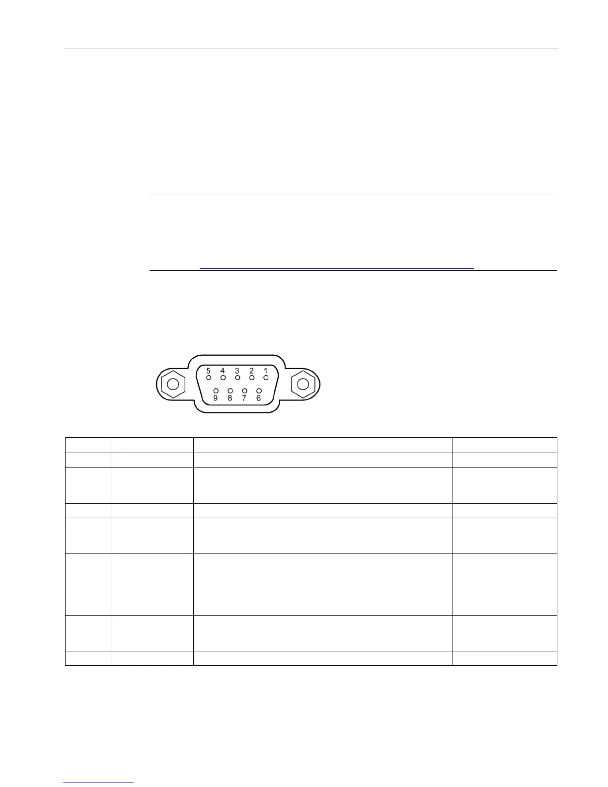
The D-sub female connector has the following pin assignment:
Socket pin 1 is not connected.
2 NC (M24) Socket pin 2 is not connected. With other MPI/DP components,
the return line of the floating 24 V power supply may be via this
Signal line B of the PROFIBUS connector.
4 RTSAS RTSAS, input signal for direct MPI link. The control signal is "1"
active when the automation system connected over a special
Input
5 M5EXT M5EXT return line (GND) of the 5 V power supply and refer-
ence potential for the signals RTSAS and RTS of the
PROFIBUS interface.
Output
6 P5EXT P5EXT power supply (+5 V) for the 5 V power supply.
(only for bus termination)
Output
7 NC (P24V) Socket pin 7 is not connected. With other MPI/DP components,
the P24V supply of the floating 24 V power supply may be via
Signal line A of the PROFIBUS connector.
 Loading...