$GGUHVVLQJ
S7-300 Automation System, Hardware and Installation: CPU 31xC and CPU 31x
A5E00105492-03
8-5
$QH[DPSOHIRUGLJLWDOPRGXOHV
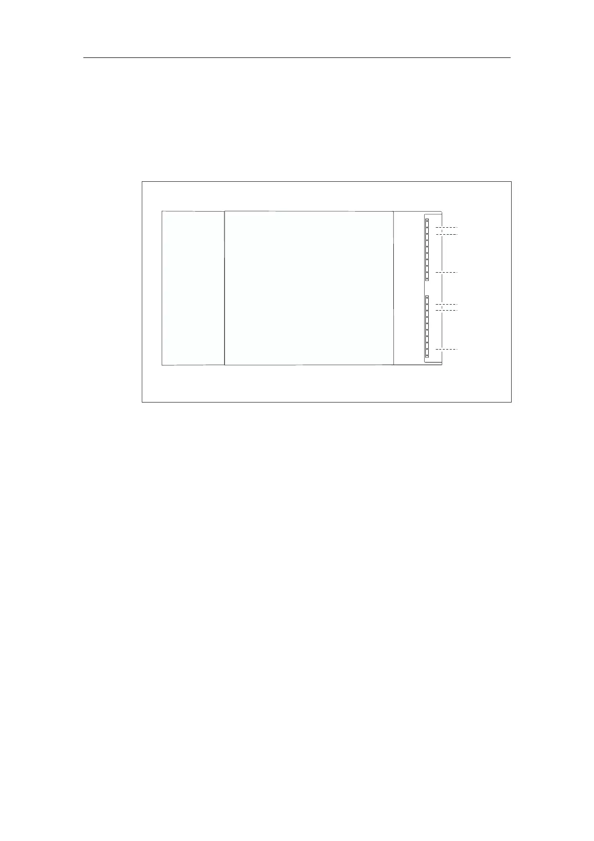
The example in the figure below shows which default addresses are obtained if a
digital module is inserted in slot 4 (that is, when the module start address is 0).
Slot number 3 has not been assigned since there is no interface module in the
example.
Slot
number
4
:
:
:
:
:
:
1
2
PS
CPU
SM
0
1
2
3
4
5
6
7
0
1
2
3
4
5
6
7
Address 0.0
Address 1.7
Address 1.1
Address 1.0
Address 0.7
Address 0.1
Figure 8-3 I/O Addresses of a digital module in Slot 4
$GGUHVVHVRIWKHDQDORJPRGXOHV
The address of an analog input or output channel is always a word address.
The channel address depends on the module start address.
Insert the first analog module into slot 4 so that it has default start address 256.
The start address of every subsequent analog module will be incremented by 16
per slot (see diagram under 6ORWEDVHGPRGXOHDGGUHVVLQJ
An analog I/O module has the same start addresses for its input and output
channels.
 Loading...


