7HVWLQJ)XQFWLRQV'LDJQRVWLFVDQG)DXOW(OLPLQDWLRQ
S7-300 Automation System, Hardware and Installation: CPU 31xC and CPU 31x
11-22 A5E00105492-03
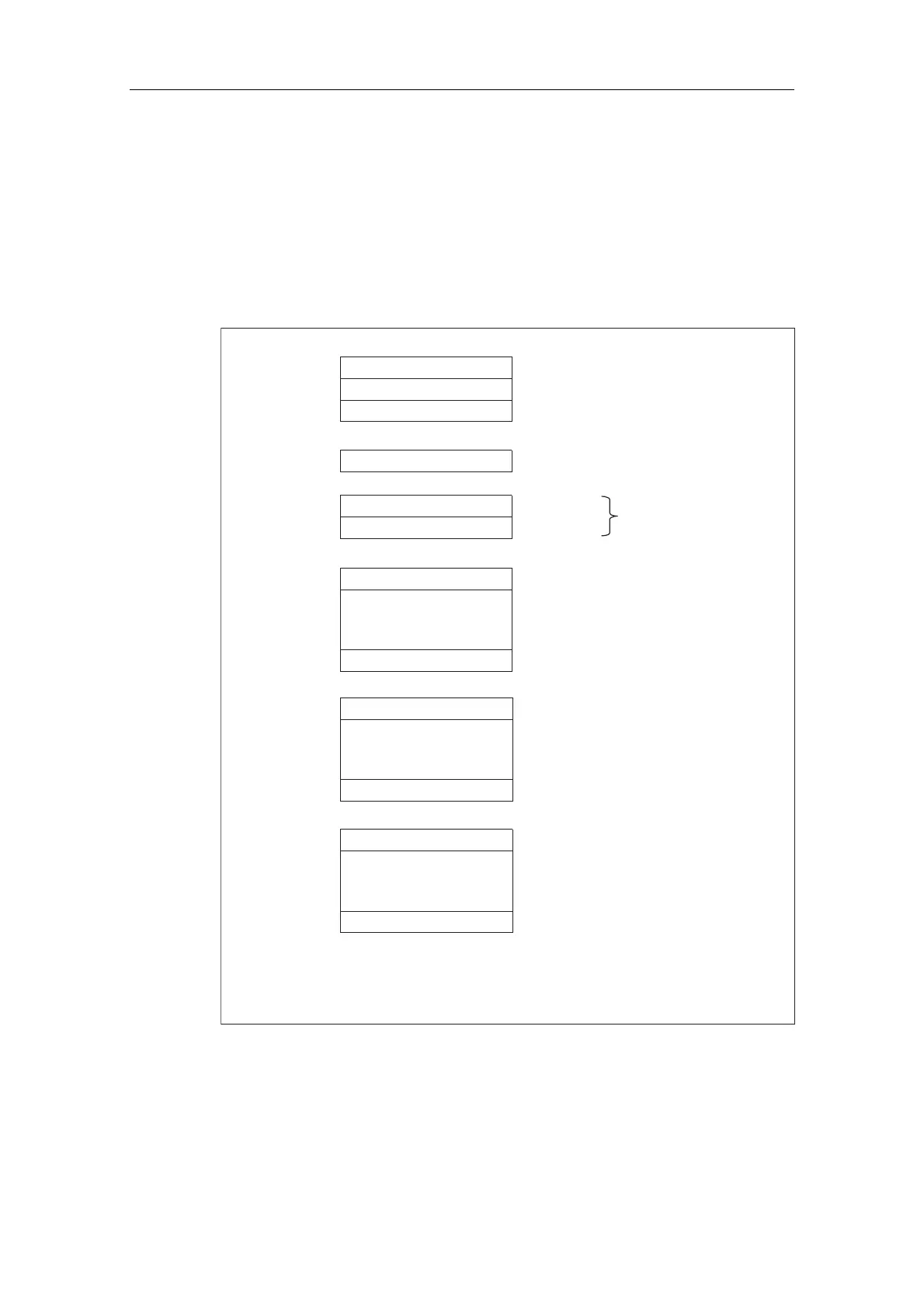
6WUXFWXUHRIWKH6ODYH'LDJQRVWLF'DWDZKHQWKH&38LVXVHGDV
DQ,QWHOOLJHQW6ODYH
6WUXFWXUHRIWKHGLDJQRVWLFVPHVVDJHIUDPH
The figure below shows the structure of the diagnostics message frame for slave
diagnostics.
Station status 1 to 3
Byte 0
Byte 1
Byte 2
Byte 3
Master PROFIBUS address
Byte 4
Byte 5
Low byte
High byte
Manufacturer ID
Byte 6
to
Module diagnostics
Byte x-1
.
.
.
(length depends on the number of the
configured areas of the intermediate
memory )
1
1
.
.
.
Modul status (device-specific diagnostics)
Byte x
to
Byte y-1
(length depends on the number
of the configured address areas)
.
.
.
Interrupt status (device-specific diagnostics)
Byte y
to
Byte z
(length depends on interrupt type)
Exception: if the DP master is wrongly configured,
the DP slave will interprete 35 configured address areas
(46
H
in byte 6)
Figure 11-6 Structure of slave diagnostic data
 Loading...


