&RQILJXULQJ
S7-300 Automation System, Hardware and Installation: CPU 31xC and CPU 31x
5-48 A5E00105492-03
,QIRUPDWLRQRQURXWLQJFDQEHIRXQGLQWKH
• &38'DWD5HIHUHQFH0DQXDOfor your CPU
• In the &RPPXQLFDWLRQZLWK6,0$7,& manual.
([DPSOH7HUPLQDWLQJUHVLVWRULQWKH03,VXEQHW
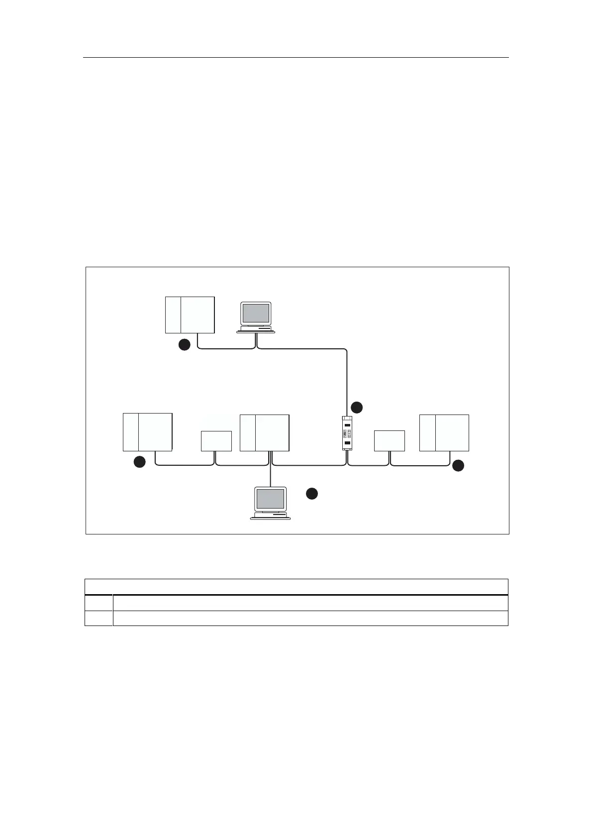
The figure below shows you an example of an MPI subnet and where to install the
terminating resistor.
The figure below illustrates where the terminating resistors must be connected in
an MPI subnet. In this example, the programming device is connected via a stub
cable during commissioning or maintenance only.
OP 27
PG
PG
RS 485-
Repeater
1
CPU
PS
ET 200 M
S7-300
CPU
PS
CPU
CPU
PS
ET 200 M
S7-300
CPU
PS
CPU
CPU
PS
ET 200 M
S7-300
CPU
PS
CPU
OP 27
CPU
PS
ET 200 M
S7-300
CPU
PS
CPU
1
1
2
1
Installing Figure 5-19 the terminating resistors in an MPI subnet
.H\WRQXPEHUVLQWKHILJXUH
Terminating resistor inserted
PG connected by means of a stub cable for maintenance purposes
 Loading...