Product characteristics
3.5 Displays
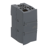
Compact Switch Module CSM 1277
Operating Instructions, V. 1.20, A2B00079397B
15
Between ports of the same group, the requirements for Environment A are met. For example
between P1 and P2.
NOTICE
Please note that the direct connection of two ports on the switch or accidental connection
over several switches causes an illegal loop. Such a loop can lead to network overload and
network failures.
3.5 Displays
Displays of the CSM 1277
Power indicator 'DIAG' (green LED)
The status of the power supply is indicated by a green LED:
Status Meaning
LED lit green Power supply is connected
LED not lit Power supply is not connected or the applied voltage is too low.
Refer to the Note in Section 4.7
Port status indicators 'P1' to 'P4' (green LEDs)
The status of the ports is indicated by four green LEDs. These are below the top panel. See
also Figure 4-4
Status Meaning
Port 1 through 4 LED lit Existing connection via port to Industrial Ethernet (LINK status)
Port 1 through 4 LED flashing Port is sending / receiving via Industrial Ethernet
Ports 1 through 4 LEDs flashing / in
sequence
Test phase during power on
 Loading...