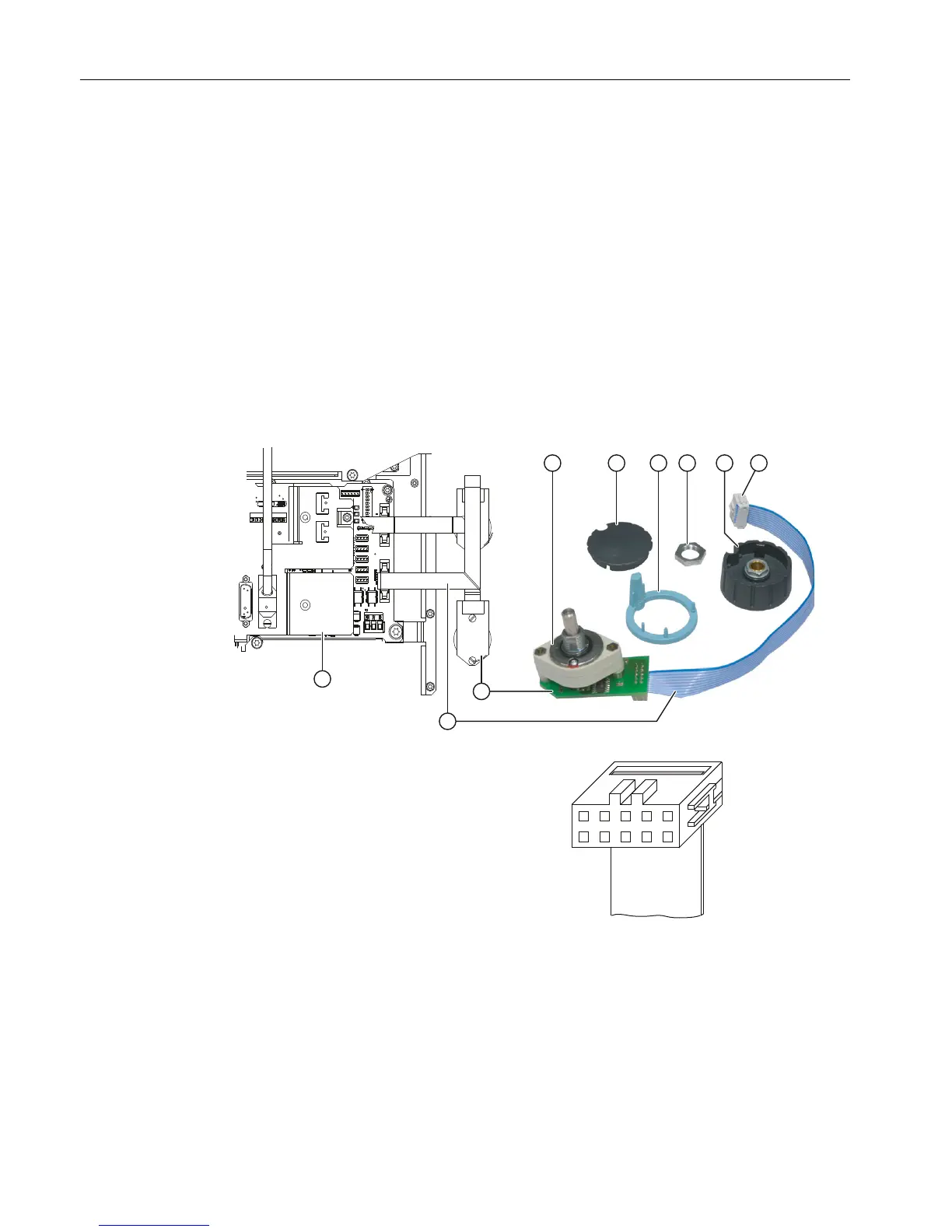
Installing the rotary switch
1. Push the O-ring ① onto the axle of the new rotary switch as a gasket.
2. Insert the rotary switch into the front cutout so that pressure is applied to the O-ring.
3. Screw the lock nut ④ onto the rotary switch axle from the front with a wrench (size 14)
(tightening torque: 3 Nm).
4. Connect the arrow ring ③ and the rotary knob ⑤.
5. Push both parts onto the axle of the rotary switch.
6. Align the arrow point on the ring with position "0" on the scale.
7. Tighten the collet nut of the rotary knob by hand and using a torque wrench tighten to a
torque of 2 Nm.
8. Place the cap ② on the rotary knob and snap it into position.
9. Fold and fasten the connecting cable ⑦ as shown in the diagram on the left.
③ Arrow ring
④ Fastening nut
⑤ Rotary knob
⑥ Connection plug
⑦ Connection cable
⑧ Connection board
⑨ COM board
Figure 8-3 Installing a rotary switch
The pin assignments of the rotary switch interfaces can be found in Section COM board IE
MCP (Page 25).
Spare parts
8.2 Replacement
ERGOline Stage 3
52 Manual, 02/2015, 6FC5397-4FP40-0BA0
 Loading...