EasyManua.ls Logo

Siemens FDCIO221 User Manual

Siemens FDCIO221
8 pages
To Next Page IconTo Next Page
Page #1 background imageLoading...
Page #1 background image
A6V10212086_k_--_--
Smart Infrastructure
2019-04-02
FDCI221 FDCIO221 FDCH221
en Input module Input/Output module Housing
de Eingabebaustein Ein-/Ausgabebaustein Gehäuse
fr Interface d'entrées Interface d'entrées / sorties Boîtier
es Módulo de entrada Módulo de entrada/salida Carcasa
it Modulo ingressi digitali Modulo in/out digitali Contenitore
en
Installation
de
Montage
fr
Montage
es
Montaje
it
Montaggio
Fig. 1 Fig. 2 Fig. 3
Fig. 4 Fig. 5
Fig. 6
7
8
Question and Answer IconNeed help?

Do you have a question about the Siemens FDCIO221 and is the answer not in the manual?

Siemens FDCIO221 Specifications

General IconGeneral
BrandSiemens
ModelFDCIO221
CategoryI/O Systems
LanguageEnglish

Summary

Installation

Installation on a Plane Surface

Mounting the module on a flat surface using screws.

Installation on a Top Hat Rail

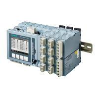
Attaching the module to a top hat rail using installation feet.

Installation in Housing

Steps to install the module inside the FDCH221 housing.

Electric Connection

Detector Line Connection

Connecting the detector line to terminals, noting polarity.

Shielded Cable Connection

Connecting shielded cables to the DBZ1190-AB terminal.

Resistor and Jumper Connections

Connecting resistors to input lines and jumpers to J1/J2.

Product Descriptions and Accessories

FDCIO221 Module

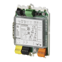
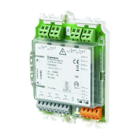
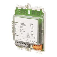
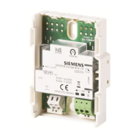
Description of the FDCI221 input/output module.

FDCH221 Housing

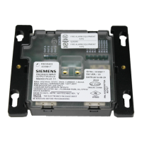
Description of the FDCH221 housing for module protection.

Mounting Foot

Details on the FDCM291 mounting foot accessory.

Cable Glands and Terminals

Information on M20 cable glands and connection terminals.

Related product manuals