4BMounting / Installation
| 138
2015-11-04
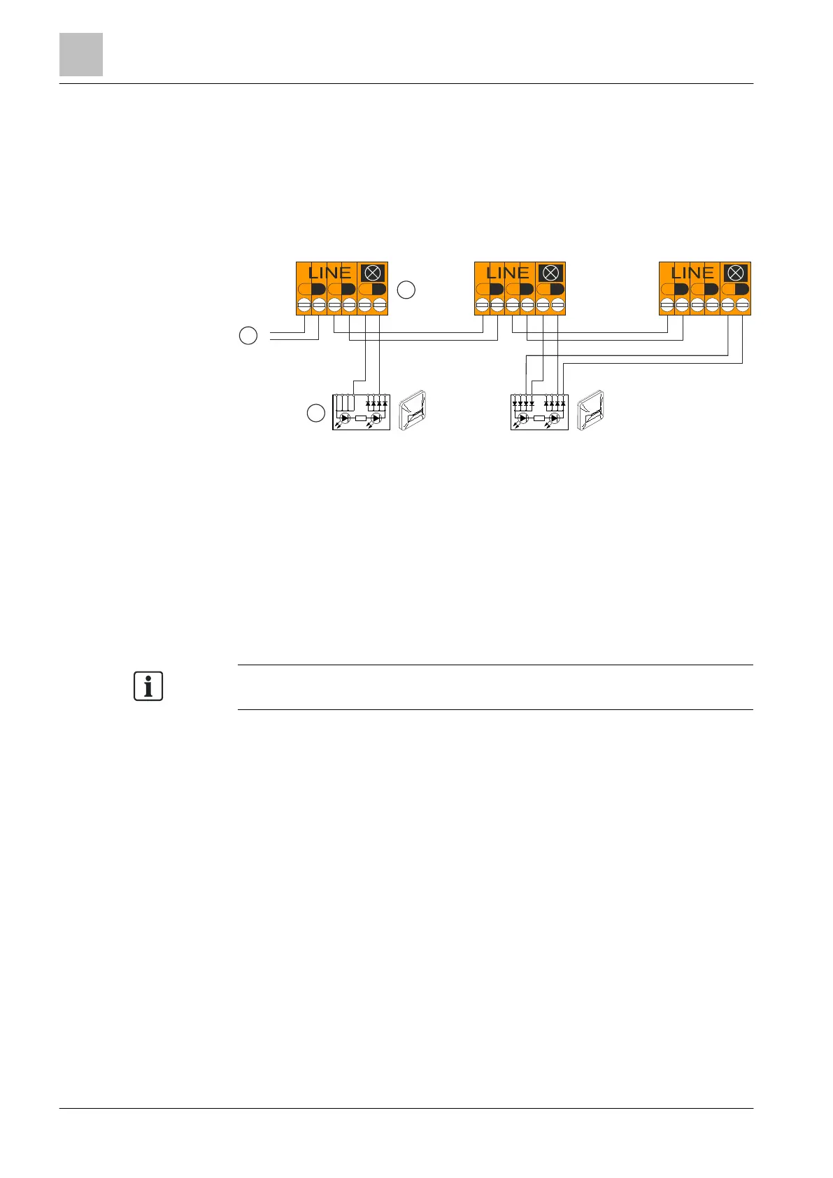
5.19.5.3 Connecting external alarm indicators
The points below apply to connecting external alarm indicators:
● If the external alarm indicator is connected to only one individual detector, there
is no limitation.
● If only original SIGMALOOP detectors and FDOOT241-A4 with base adapter
FDB241 are used, there is no limitation.
● If several FDOOT241-A4 are merged with Sinteso detector base FDB22x on an
external alarm indicator, the external alarm indicator FDAI9x must be used.
Connecting external alarm indicators
1
Control panel 3
External alarm indicator
2
Sinteso detector base FDB22x
5.19.6 Connection diagram for interactive detector line
The existing cabling can be transferred for interactive detectors.
The multiple protocol detector must be installed in the detector base DB1151A
using a base adapter FDB251.
Connecting an external alarm indicator to the base adapter FDB251 is not
permitted according to EN 54.
+
-
+
-
+
-
+
-
+
-
+
-
LINE
+
-
+
-
+
-
FDAI9x
+
-
+
-
+
-
1
2
3