EasyManuals Logo

Siemens Flowrite 599 Series User Manual

Siemens Flowrite 599 Series
17 pages
To Next Page IconTo Next Page
To Previous Page IconTo Previous Page
Page #12 background imageLoading...
Page #12 background image
Technical Instructions Flowrite 599 Series Two-Way Valves, 1/2 to 2-Inch, Bronze Body, ANSI 250
Document Number 155-184P25
May 2, 2016
Page 12 Siemens Industry, Inc.
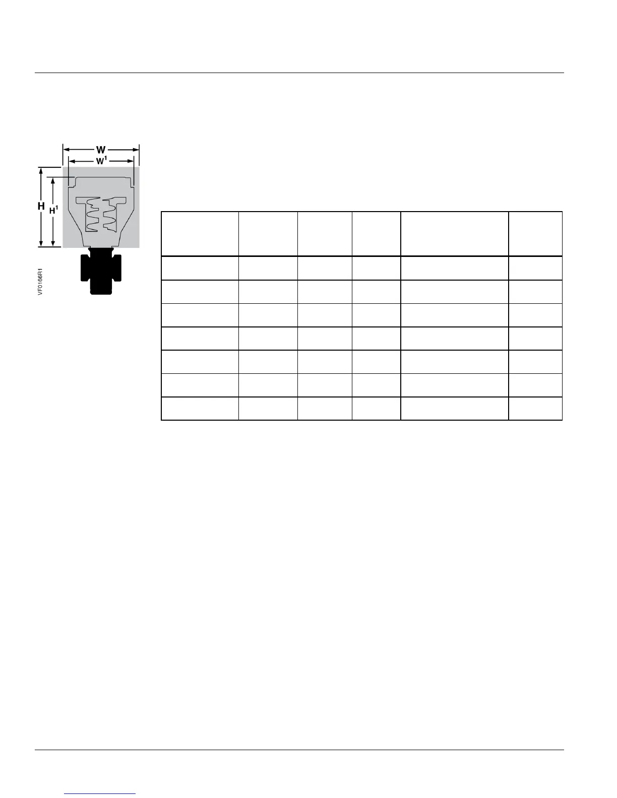
Dimensions
Figure 6.
The letters in Figure 6 refer to actuator and service envelope dimensions in
Table 10.
See Table 11 for valve body dimensions.
Table 10. Dimensions of the Actuator and Recommended Service Envelope.
Dimensions in Inches (Millimeters).
Actuator
Actuator
Prefix
Code
Actual
Height of
Actuator
H1
Service
Height
H
Actual Width or
Diameter of Actuator
W1
Service
Width
W
4-inch
Pneumatic
268, 269
270
5-3/4
(146)
14
(350)
5-1/2 (137)
diameter
18
(450)
8-inch
Pneumatic
277, 278
283, 284
14-1/8
(359)
26
(660)
8-3/4 (222)
diameter
21
(533)
12-inch
Pneumatic
279, 285
17-7/8
(454)
30
(762)
15-1/8 (384)
diameter
27
(686)
SAX
371, 373
9-9/16
(242)
17-1/4
(442)
4-7/8 (124) Width
5-7/8 (150) Depth
17-3/4
(450)
Rack and Pinion
298, 299
14-1/2
(368)
24-1/2
(622)
5 (127) Width*
5-1/8 (131) Depth
13
(331)
SKD
267, 274
275, 276
11-13/16
(300)
19-3/4
(500)
5 (127) Width
6-5/8 (169) Depth
14-1/2
(360)
SKB
289, 291,
290
14-3/4
(375)
22-3/4
(578)
7 (178) Width × 8-15/16
(226) Depth
25
(635)

Questions and Answers:

Question and Answer IconNeed help?

Do you have a question about the Siemens Flowrite 599 Series and is the answer not in the manual?

Siemens Flowrite 599 Series Specifications

General IconGeneral
BrandSiemens
ModelFlowrite 599 Series
CategoryControl Unit
LanguageEnglish

Related product manuals