Network module (SAFEDLINK) FN2001
1
5
Siemens Industry, Inc. A6V10315042_f_en_--
Building Technologies Division 2015-04-16
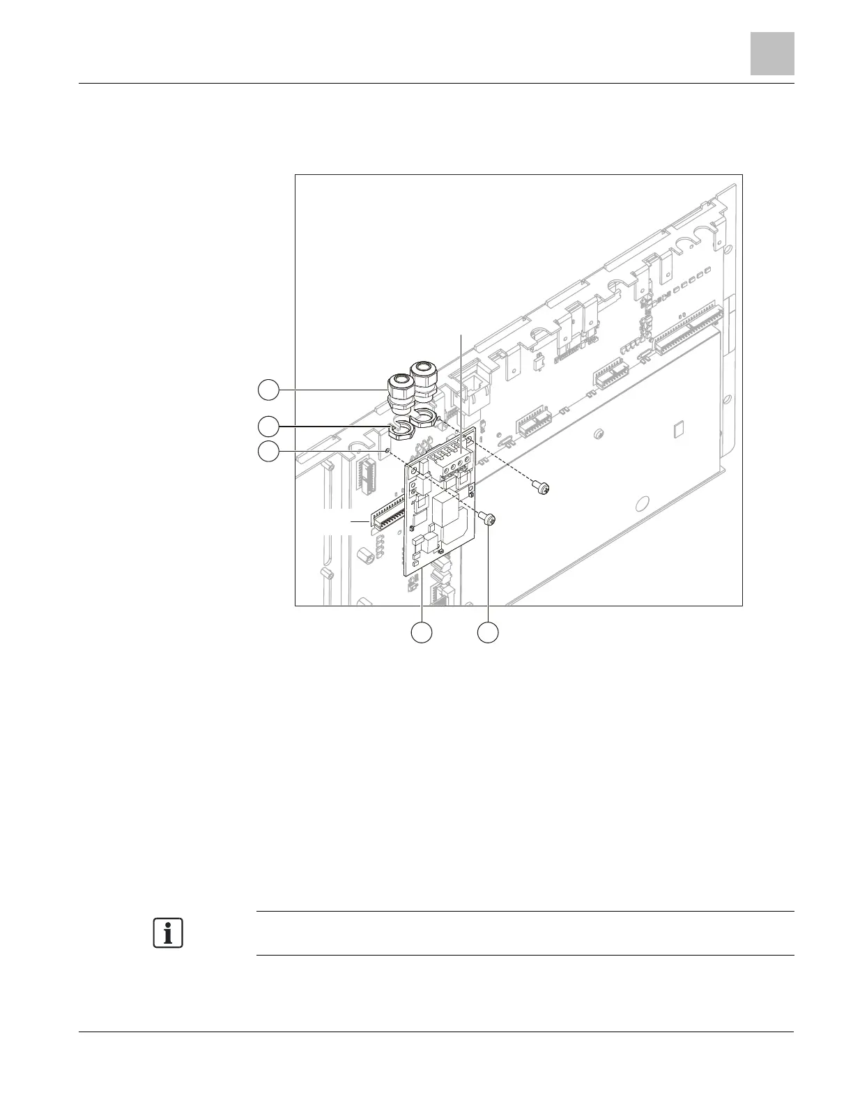
1.2 Installation
The network module (SAFEDLINK) FN2001 must be installed in the left slot (X13)
(main module slot).
45
X3
1
2
3
X13
Installing the network module (SAFEDLINK) FN2001
1 Fastening tabs on operating unit
2 Nut for screwed cable gland (2 per module)
1
3 Cable gland (2 per module)
1
4 2x fixing screw
5 Network module (SAFEDLINK) on X13 (master module)
X3 FCnet/SAFEDLINK or C-WEB/SAFEDLINK connection terminal
X13 Connection terminal on PMI & mainboard
1
When using shielded cables, the cable glands are needed to secure the shielding.
Make sure you install the network module (
) in the correct position (plug
X13) during installation.
 Loading...


