16/24
Building Technologies Division CC1N7153en
21.09.2016
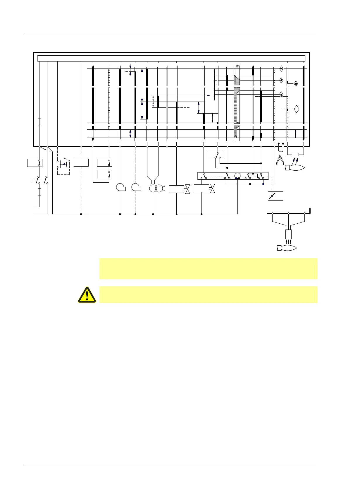
Connection diagrams (for variants, refer to «Connection examples»)
LAL1
H
N
t3n
t3´
C
D
A
L
EK2
AL
21
1
AS
2
1(3)
3
W
R
4 5 6 7
t6
B
A
t7
BV2
BV1
Z
SA
15
16
17 18
a
z
M
2019 9
LR
t4
t3
TSA
t5
t1
t12
t16
t11
a
z
23
m
11 10
8
22
B
t13
1
v
7153a01/0814
LK
Si
QRB...
sw
bl
br
QRC1...
23
22
1
SB
M1
M2
Note!
In applications involving air heaters (WLE), or in the case of oil burners with a
maximum throughput of > 30 kW/h, removing wire link B is not permitted.
Caution!
Do not press lockout reset button (EKx) for more than 10 seconds!
 Loading...


