6 CC1N7761E
AS Unit fuse L2 Lockout warning device, external
AR Working relay with contacts «ar...» L3 Signal lamp for the flame indication
BR Lockout relay with contacts «br...» LK Air damper actuator with limit or auxiliary
BS1 Operating switch switches
BS2 Operating mode selector switch (see also «Connection examples»)
BV... Fuel valve a = actuator runs into position «Open»
(BV...) Fuel valve for a pilot burner which is switched (maximum air volume)
off on completion of the 2nd safety time z = actuator runs into position «Closed»
c... Fan contactor with contacts «c...» (minimum air volume)
d... Auxiliary relay with contacts «d...» LP Air pressure monitor
e... Thermal overload fuse M... Fan
EK1 Reset button at the unit NTC High-temperature conductor (delay unit)
EK2 Remote reset button OV... Oil valve
FE Flame detector electrode Q Temperature or pressure detector
FR Flame relay QRA... UV-detector
FW Contacts of the flame safeguards LAE10..., R... Thermostat or pressurestat
LFE10... or LFE50... RAR... Selenium photocell detector
GP Gas pressure monitor RV Control valve
GV... Gas valve SB Safety limiter
H Main isolator SM Synchronous motor of the switching
HR1 Auxiliary relay with contacts «hr11 and hr12» mechanism
HR2 Auxiliary relay with contact «hr21» SQ... Type reference of air damper actuator
HR3 Auxiliary relay for flame detector or flame UL1 Operating switch for motor of the switching
simulation test mechanism
L1 Lockout warning device, built-in UL2 Changeover link for
«Short/long pre-ignition time»
UL3 Changeover link for «STOP» or «Run» of
the sequence mechanism after a lockout
W Limit thermostat or pressure monitor
Z Ignition transformer
* Do not press EK longer than 10 s
T 120 s Running time of the switching mechanism
t1 8...63 s Pre-purge time, adjustable
t2 0...9 s 1st safety time, adjustable (set to 0 s with ignition spark supervision)
t2z 0...6 s Safety time for the pilot burner in case of burner start-up with
ignition spark supervision
t3 t11 + t1 + t12 + 7 s Pre-ignition time «Long» (during the whole pre-purge)
t3’ 3 s Pre-ignition time «Short»
t4 11 s Interval between release of the 1st and 2nd fuel valve
t5 12 s Interval between release of the 2nd and 3rd fuel valve or the load
controller
t6 T- (30 + t1) Post-purge time
t7 3 s Delay time
t8 t1 + 30 + t11 + t12 Total start-up time
t9 0...9 s 2nd safety time with interrupted pilot burner
t10 10 s Bridging time (set time for the air pressure control)
t11, t12 optional Opening or closing time of the air damper
Maximum permissible after-burn time
(counted as of the beginning of t6) 7 s
For the factory setting of the different types, please refer to the type summary.
Legend
for the entire data sheet
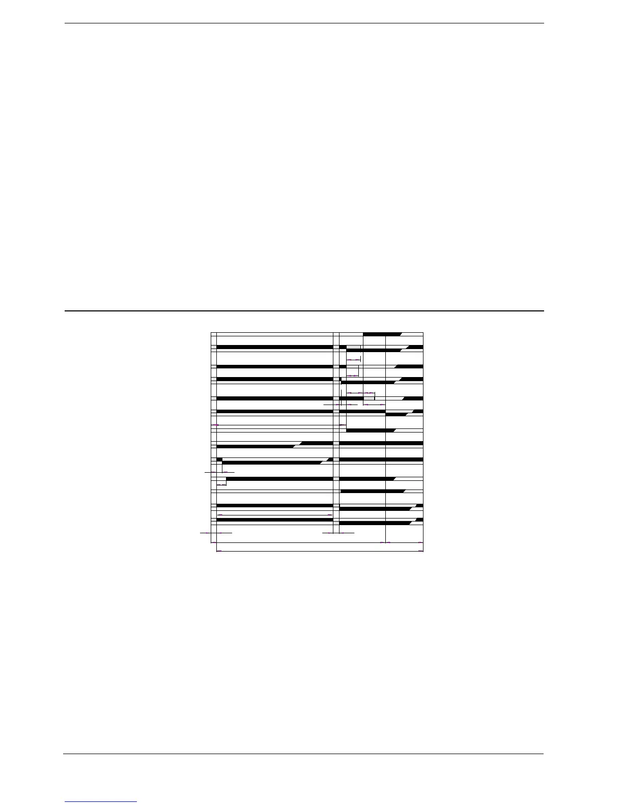
Time Diagram of the
Switching Mechanism
t3
t7
t10
t1
t11
t8
T
t12
t6
t2
t4 t9
t3´ t5
3
63
66
70
93
90
67
79
81
a
b
a
b
a
b
a
b
a
b
a
b
a
b
I
II
III
IV
V
VI
VII
VIII
IX
X
XI
XII
XIII
7761d01/0696
t2z
10
Switching times

 Loading...


