11/25
Building Technologies Division CC1N7451en
20.11.2017
Technical data (cont'd)
Voltage at the ionization probe
- Operation
- Test
C 330 V ±10 %
C 380 V ±10 %
Short-circuit current max. 0.5 mA
Recommended range of measuring
instrument
0...50 µA
Perm. length of detector cable
- Normal cable, laid separately ²)
- Shielded cable
max. 80 m
max. 140 m (e.g. high-frequency cable;
shielding connected to terminal 22)
Required detector current in operation min. 6 µA
Possible detector current in operation max. 200 µA
Supply voltage
- Operation
- Test
C 330 V ±10 %
C 380 V ±10 %
Required detector current min. 70 µA
Possible detector current
- Operation
- Test
max. 700 µA
max. 1000 µA ¹)
Perm. length of detector cable
- Normal cable, laid separately ²)
- Shielded cable
max. 100 m
max. 200 m (e.g. high-frequency cable;
shielding connected to terminal 22)
¹)
During the prepurge time with higher test voltage: Self-ignition and extraneous light test
²)
Multicore cable not permitted
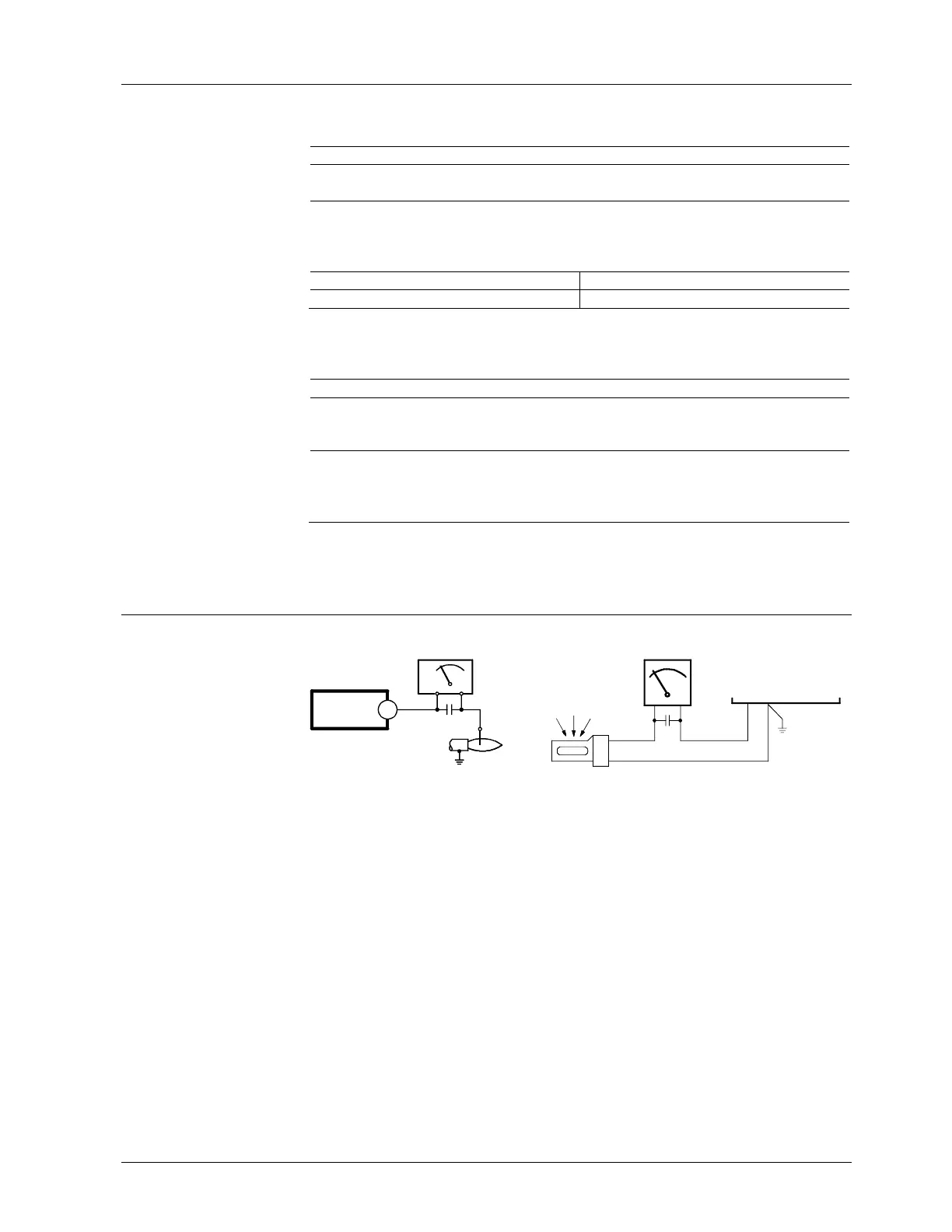
Detector current measurement
Ionization probe Flame detector QRA2 / QRA4 / QRA10
LFL1...
24
7451v01/0204
M
C
+
+
-
ION
7451v02/0204
A
M
C
23
22
LFL1...
-
+
-
+
QRA...
For detector currents, refer to «Technical data».
C Electrolytic condenser 100...470 µF; DC 10...25 V
ION Ionization probe
M Microammeter Ri max. 5,000
Flame supervision with
ionization probe
Flame supervision with
flame detector QRA2 /
QRA4 / QRA10
Measuring circuit for
detector current
measurement
Legend
 Loading...