Landis & Staefa Division CC1N7421E December 04, 1998 11/16
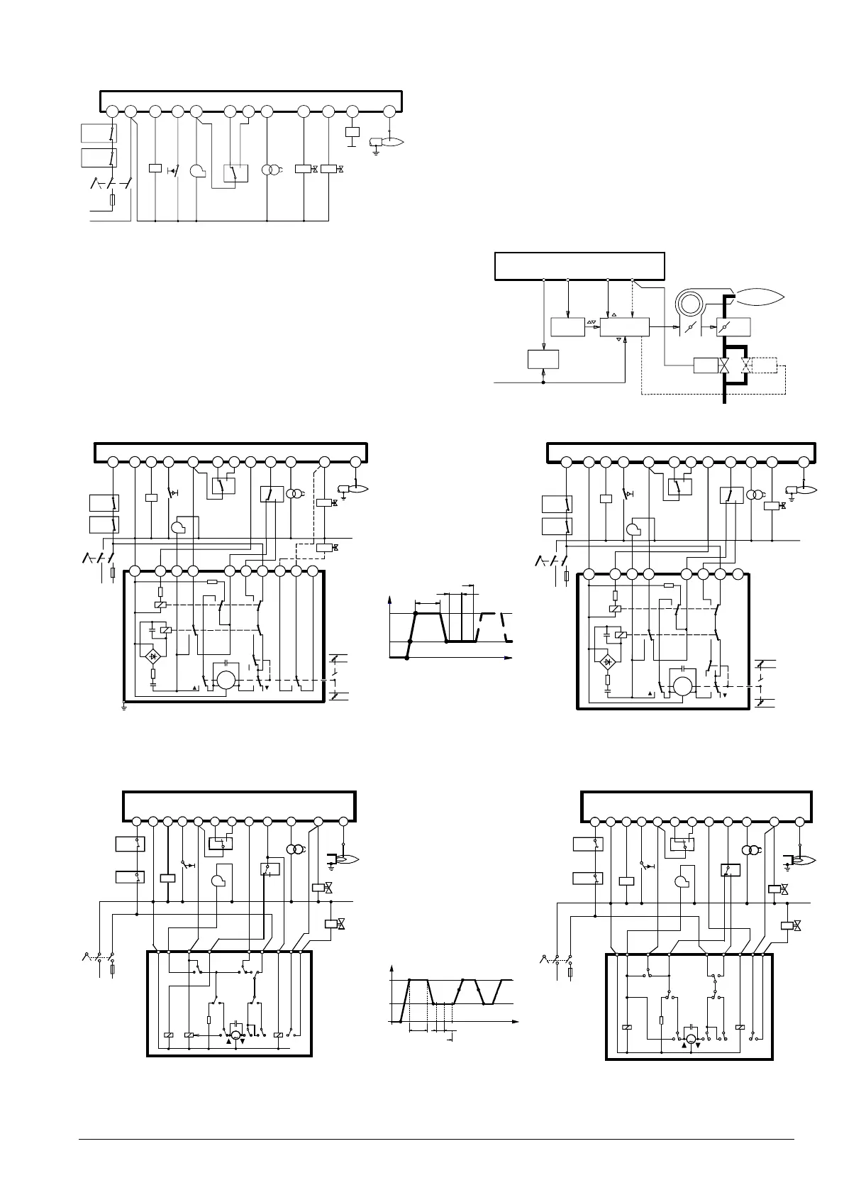
Connection diagram
LMG22...
Application examples
Control of actuators of two-stage or two-stage modulating burners.
Checked pre-purging «t1» with nominal load air volume.
For information about actuators «SA»:
SQN3...: refer to data sheet 7808
SQN7...: refer to data sheet 7804
SQN9...: refer to data sheet 7806
SQN3...151... or SQN3...251... SQN90.220... / two-stage modulating control
* Note:
with two-stage modulating burners (with gas regulation
damper «RV»), «BV2» and the dotted connection between
terminals (*) are not required
SQN7...454 / two-stage control, SQN7...424 / two-stage control,
single-wire control two-wire control
12
2
10
8
3
6
11
7
4
5
1
GP/SB
R/W
HS
0
I
L
N
AL
EK2
M
LP
Z
BV2
FE
7421a15/0598
BV1
9
SA
LMG22...
LMG2...
4
9
5
LR
SA
L
SB/R/W
BV1
RV
BV2
7421a19/1098
12
12 2
10
8
3
6119 5 7
*
4
1
GP/SB
R/W
AL
EK2
M
LP
LR
Z
BV1
FE
BV2
*
*
L
N
0
I
HS
N8
1
2
756 34
9
7421a13
/10
98
LK
RV
SA
R1
K2
C2
K1
+
R3
D
-
+
R2
C1
I
MS
C3
III
II
V
LMG22...
KL
Zu
III
LKP
NL
t1
III
t
7421d04/0498
I
II
t4
TSA
12 2
10
8
3
611
9
5
7
4
1
GP/SB
R/W
AL
EK2
M
LP
LR
Z
BV1
FE
HS
0
I
N
L
6
8
10
21
3
7
9
7421a14/0598
RV
LK
SA
R1
K2
R3
C2
K1
+
D
-
+
R2
C1
I
MS
C3
III
II
LMG22...
LKP
zu
KL
NL
t
IIIIII
IVIV
II
II
t1
TSA
t4
N
I
HS
L
LMG 22...
R/W
GP/SB
12
EK2
38
Z
LR
5
FE
BV1
BV2
0
7421a17/
10
98
B
CA
a1
b1
c1
b2
a2
M
7
9
102
N5 4 1
3
2867
IIIII IVI
6 11
AL
4 1
M
LP
4N15
N
I
HS
L
A
b1
a1
LMG22...
R/W
GP/SB
12
AL
EK2
38
3
2
68
7
b2
a2
M
B
Z
LR
FE
BV1
41
0
12
7421a18/
10
98
10 9 5 7
BV2
IIIIIIIV
2 6 11
LP
M
 Loading...
