10/16 CC1N7421E December 04, 1998 Landis & Staefa Division
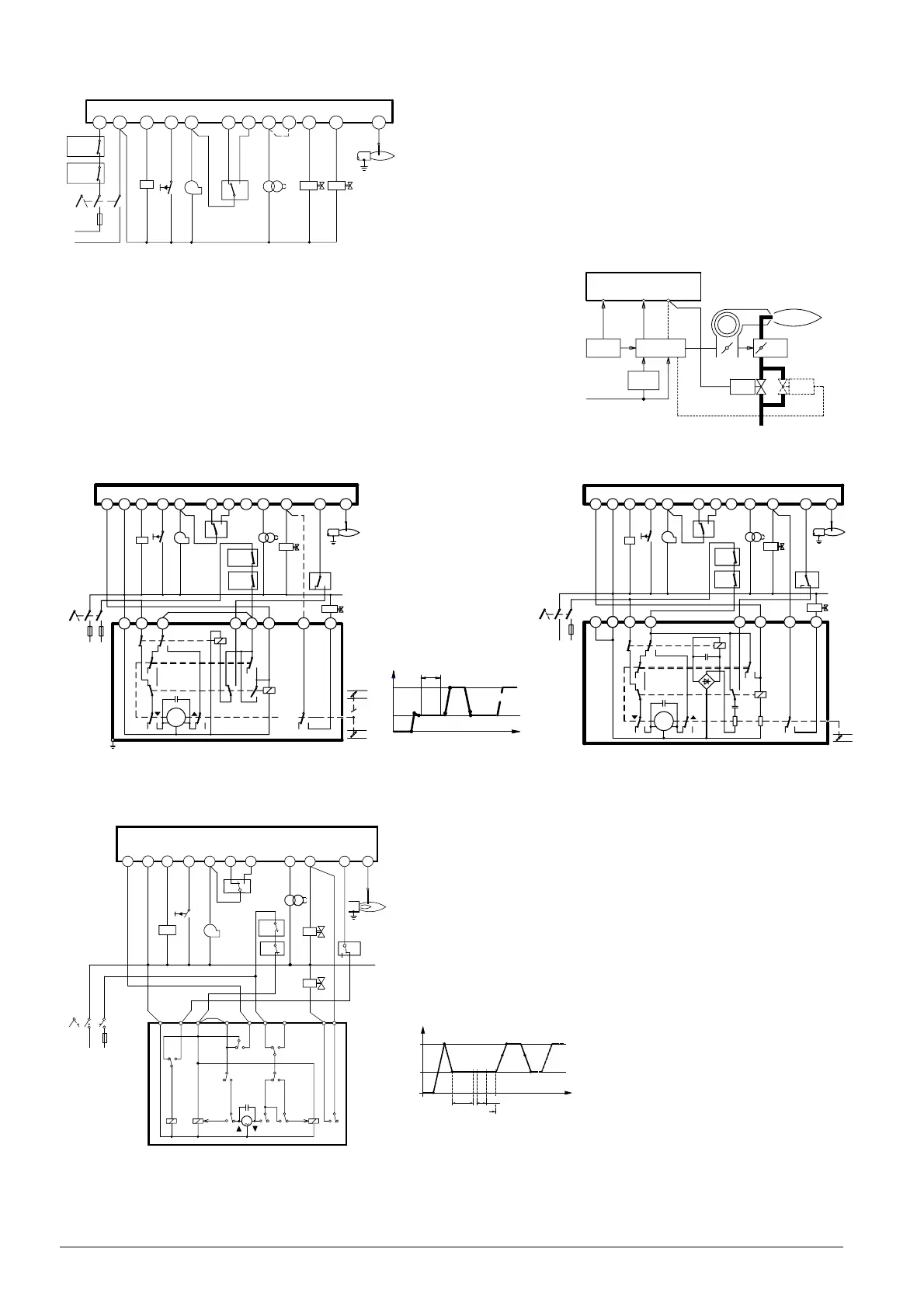
Connection diagram
LMG21... / LMG25...
Application examples
Control of actuators of two-stage or two-stage modulating burners.
Checked pre-purging «t1» with low flame air volume.
Exactly the same low flame actuator positions during startup and operation!
For information about actuators «SA»:
SQN3...: refer to data sheet 7808
SQN7...: refer to data sheet 7804
SQN9...: refer to data sheet 7806
SQN3...121... / two-stage control SQN91.140... / two-stage control
* Note:
with two-stage modulating burners (with gas regulation
damper «RV»), «BV2» and the dotted connection between
terminals (*) are not required
SQN7...244 / two-stage control
¹) Wire link required only with LGB21..., not with LMG21... / LMG25...
12
2
10
8
3
6
11
7
4
5
1
R/W
GP/SB
HS
0
I
L
N
AL
EK2
M
LP
Z
BV2
FE
7421a06/0598
BV1
LMG21.../25...
9
1)
LMG2...
4
12
5
LR
SA
ON/OFF
L
SB/R/W
BV1
RV
BV2
7421a07/1098
12
2
10 8
3
6
11
9
7
451
HS
0
I
NL
AL
EK2
M
LP
GP/SB
R/W
Z
BV1
(*)
LR
FE
BV2
*
(*)
N
1
2
67
5
4
3
b1
b2
B
ab
III
a3
ab
II
MS
I
ab
a2
a
b
IV
A
ab
V
RV
LK
7421a03/1098
LMG21.../22.../25...
12
2
10
83
6
11 7
4
51
AL
EK2
M
LP
GP/
SB
R/W
Z
BV1
LR
FE
BV2
HS
N
L
0
I
NN
1
25
3
64
7421a08/1098
LK
SA
IV
II
MS
I
C3
D
K2
C31
III
R32
R1
V
K1
a
b
ab ab ba
a
b
-
+
+
LMG 21.../22.../25...
II
KL
Zu
III
LKP
NL
t1
IV
III
IV
I
t
IV
7421d03/1098
9
1
b1
LP
HS
8N
4
N
I
L
B
a1
A
LMG21.../22.../25...
12
EK2
AL
2
10
3
5
3
2
76
b2
a2
M
c1
C
R/W
GP/
SB
6
11 4
FE
5
1
0
7421a09/1098
8
IIIII IVI
Z
BV1
LR
7
BV2
M
I
KL
zu
NL
LKP
t
I
III III
IV IV
II
TSA
t4
t1
 Loading...
