3
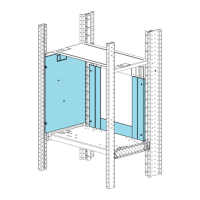
Figure 2
Rear View of the ACM-RK
TBM-2
TMM-1
MMM-1
P1
P3
P5
P7
P8
P6
P4
NEW CABLE FROM
CABLES-RK KIT
TO MMB-2
NEW CABLE FROM
CABLES-RK KIT
EXTENSION FROM
CABLES-RK KIT
EXISTING
MMM-1 CABLE
TO ANN-1
(MKB-RK)
ACM-1
ACM-RK
PIM-1
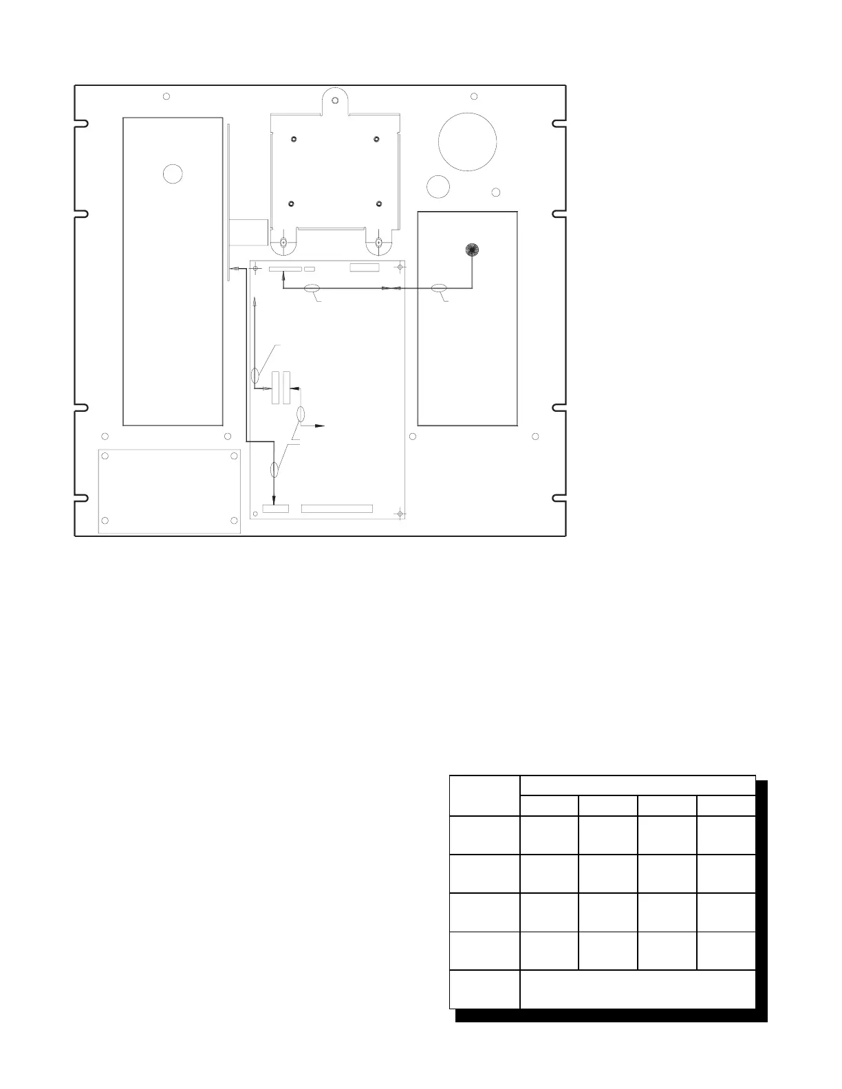
switch S1 to set the network address of the
MKB-3. Refer to Table 3 for switch settings.
2. The MKB-3 module address is always set
within network addresses 248 through 251.
3. One supervised MKB-3 must be installed
at network address 251. Other supervised
MKBs may be at the other addresses.
NOTE: Switches S1-SW3 and S1-SW4 are for
future use. Switch S1-SW5 is used to
select supervision.
Setting Supervision
Use switch S1-SW5 on the ANN-1 to select or
deselect supervision. If your ANN-1 has a switch
with position 1 indicated on the left-hand side,
ignore the printing on the switch. SW1 on S1 is at
the extreme right-hand side of S1, regardless of
any other marking.
To set for supervision
S1-SW5 = Closed (ON)
To set for non-supervision
S1-SW5 = Open (OFF)
NOTE: When you select non-supervision for an
annunciator, there must also be one and
only one supervised annunciator at the
same address. The supervisory mode is
independent of the network address.
TABLE 3
SWITCH SETTINGS ON THE ANN-1
SWITCH
ADDRESS SETTINGS FOR:
248 249 250 251
S1-SW1
Open-
OFF
Closed-
ON
Open-
OFF
Closed-
On
S1-SW2
Open-
OFF
Open-
OFF
Closed-
ON
Closed-
ON
S1-SW3
Closed-
ON
Closed-
ON
Closed-
ON
Closed-
ON
S1-SW4
Closed-
ON
Closed-
ON
Closed-
ON
Closed-
ON
S1-SW5
See Setting Supervision