Mounting / Installation
5
43
Building Technologies A6V10316298_e_en_--
Fire Safety 2014-05-21
5.8 Cable entry
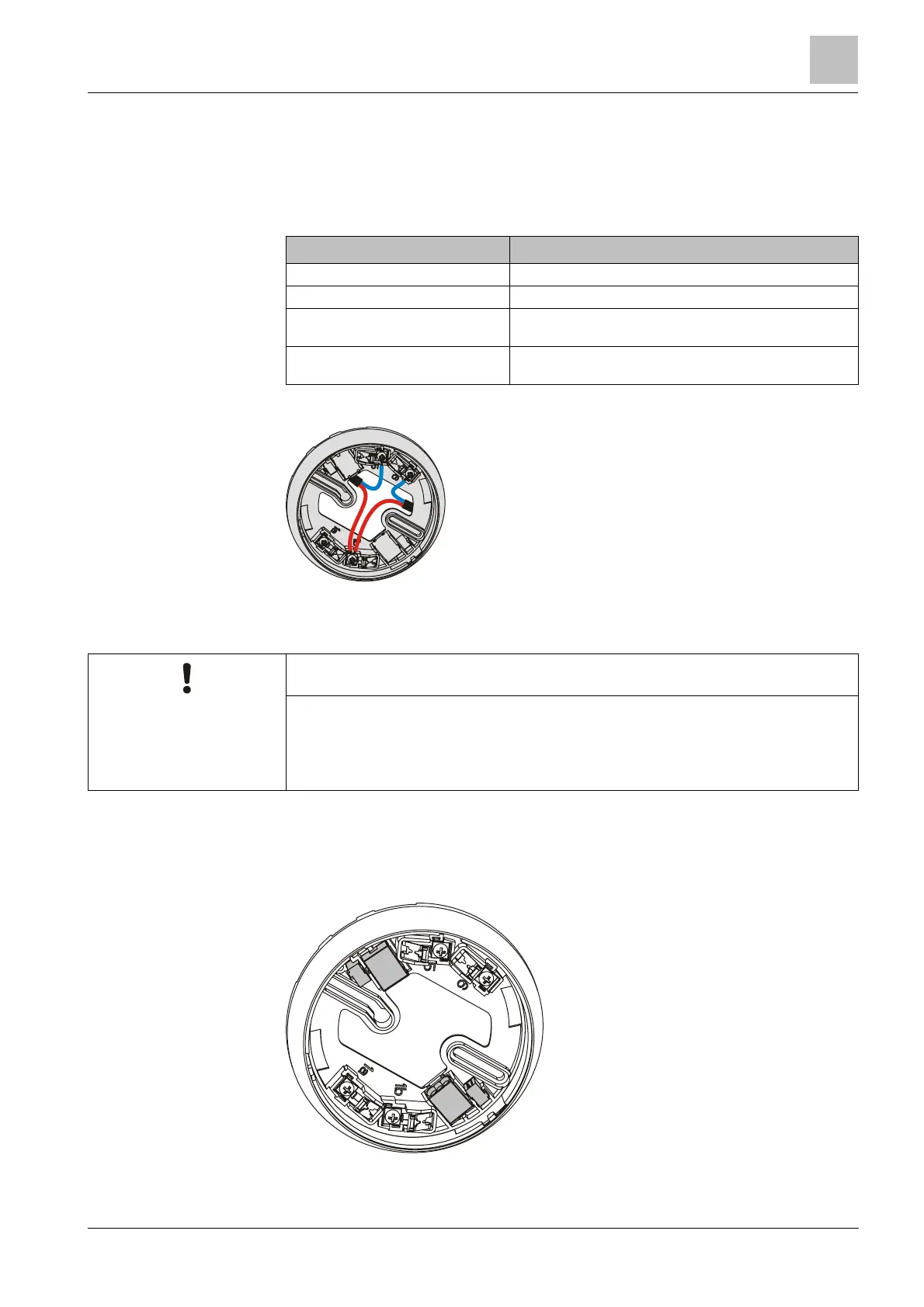
The detector bases DB110, DB110x and DB110xx feature four screw terminals. A
maximum of 2 cables may be connected to each screw terminal.
The cable cross section of the screw terminals is 0.2…1.6 mm
2
.
Terminal name Connection
1a +Connection for external alarm indicator
1b +Collective detector line IN and OUT
5 -Collective detector line IN (from the control panel) / -
external alarm indicator
6 -Collective detector line OUT (from the EOL) / -external alarm
indicator
NOTICE
Incorrect laying of cables
Damage to cables and difficulties when installing the point detector
● The cable loops must be placed flat in the base bottom.
The bare length of the cables is approximately
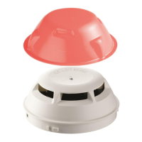
5.8.1 Auxiliary terminals DBZ1190-AA/-AB
Use the following auxiliary terminals for multiple connections:
l DBZ1190-AB connection terminal 1…2.5 mm²
l DBZ1190-AA micro terminal 0.28…0.5 mm²
Detector base with connection terminals and micro terminals