OpenAir GEB Series Enhanced Rotary Non-Spring Return Damper Actuators Technical Instructions
Document Number A6V12029156
December 16, 2021
Siemens Industry, Inc. Page 7
The type of actuator required depends on several factors:
1. Obtain damper torque ratings (ft-lb/ft
2
or Nm/m
2
) from the damper manufacturer.
2. Determine the area of the damper.
3. Calculate the total torque required to move the damper:
Total Torque =
SF
AreaDamper Rating Torque
1
1
Safety Factor: When calculating the total torque required, a safety factor should be included
for unaccountable variables such as slight misalignments, aging of the damper, and so on. A
suggested safety factor is 0.80.
Mounting and
Installation
• Place the actuator on the damper shaft so that the front of the actuator is accessible.
(The label and the manual override button are on the front side.)
• The minimum damper drive shaft is 3/4-inches (20mm). The shaft length determines
whether the shaft adapter will be mounted on the front or back of the actuator.
• See Specifications for minimum and maximum damper shaft dimensions.
• Set auxiliary switches, DIP switches, and Offset/Span as required by your
application. (See following sections for details.)
• The position indicator can be mounted to show either the clockwise or
counterclockwise 0 to 90 scale.
• A mounting bracket is included with the actuator.
• The shaft adapter and mounting parts are shipped in a separate container with the
actuator.
• The actuator is shipped from the factory with a 5° pre-load to ensure tight damper
close off.
• Detailed mounting instructions are included with each actuator.
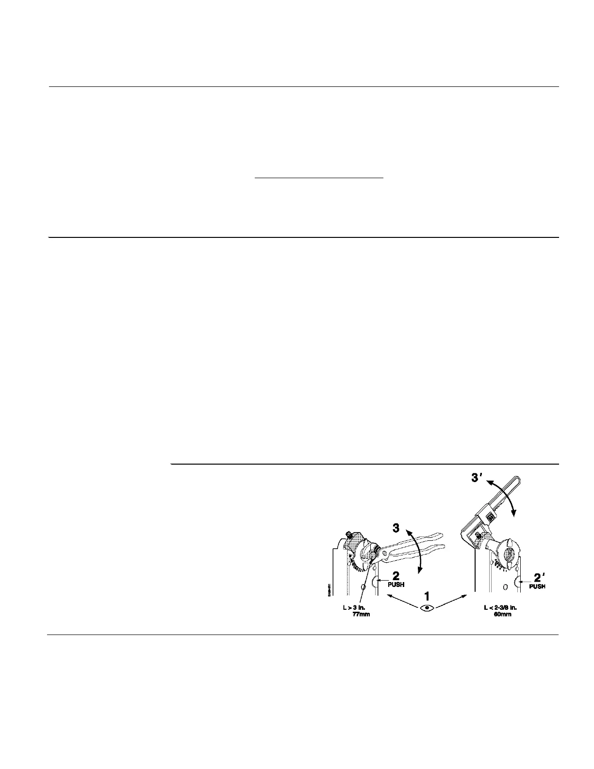
To move the damper blades
and lock the position without
power present:
1. Hold down the PUSH
button.
2. Make adjustments to the
damper position.
3. Release the PUSH button.
Once power is restored, the
actuator returns to automated
control.
Figure 8. Manual Override.
 Loading...