14/44
Siemens Rotary actuators without spring return GBB/GIB..1 CE1Z4626en
Smart Infrastructure Technical design 2019-11-28
3.3 Auxiliary switches and positioning signals
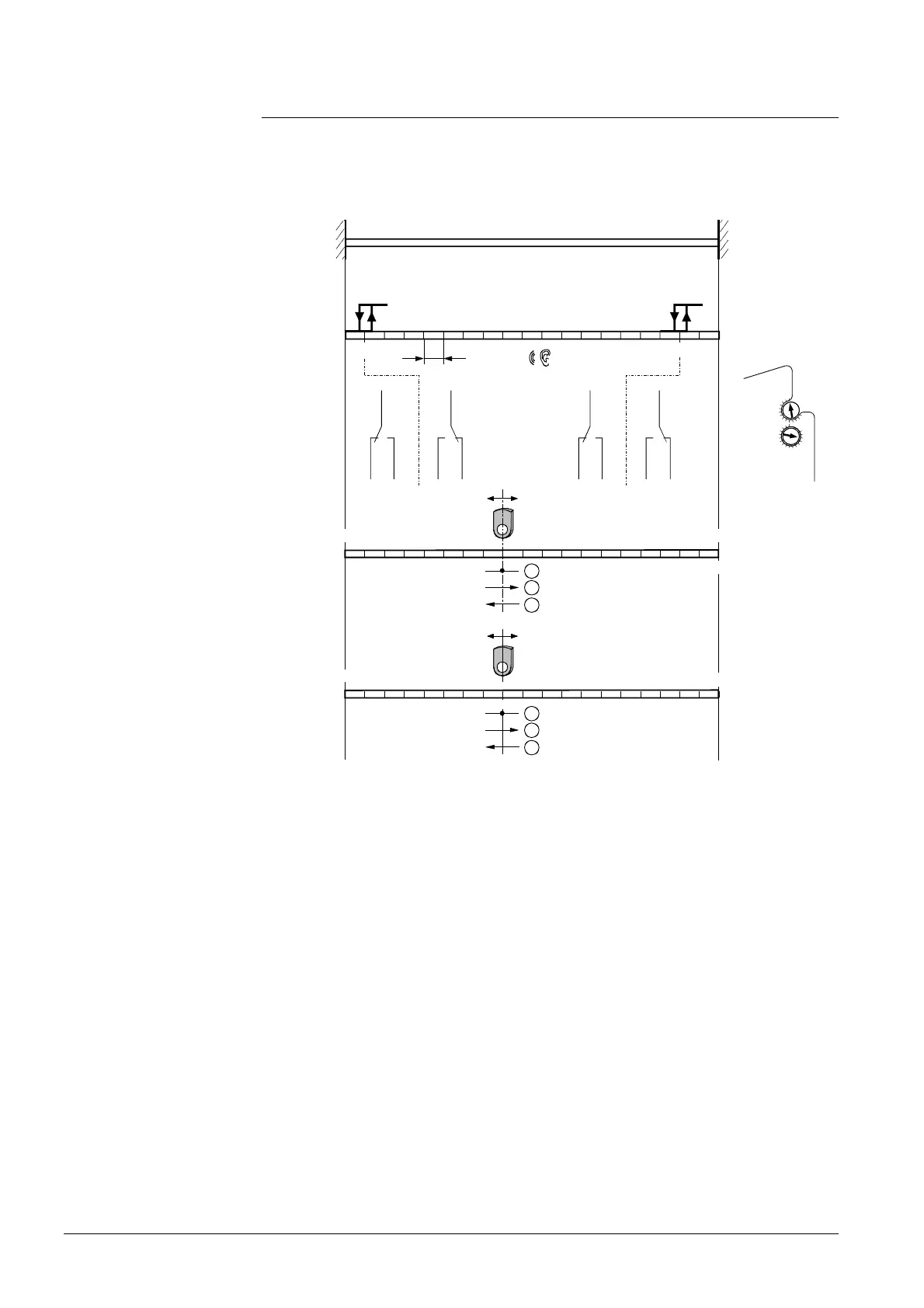
The illustration below shows the relationship between the angular rotation, the
adjustable switching points for auxiliary switches A and B and the positioning signal.
Gear train angular range
Inner mechanical limits
A B
85°
0°
0°
95°
10V
95°
5°
0° 95°
Þ 1 x click
S1 S1 S4 S4
S2 S3 S2 S3 S5 S6 S5 S6
(Q12)
(Q14)
(Q14)
(Q12)
(Q22)
(Q24)
(Q22)
(Q24)
(Q11)
(Q11)
(Q21)
(Q21)
5°
4621D04
1
2
3
4
5
6
80
70
60
50
B
90
Aux Switch
Adjustment 20
30
40
10
20
40
A
70
4637Z07
Auxiliary switches
Factory setting:
A = 5°; B = 85°
Setting range 5°…90°
Switching states
Rotary movement as a function
of the positioning signal
Modulating signal, DC 0…10 V
AC 24 V
No movement (G, G0, Y=U)
Opening (G, G0,Y>U)
Closing (G, G0, Y<U or G,
G0)
Three-position signal,
AC 24 V; AC 230 V
No movement (no voltage)
Opening (G, Y1 or N, Y1)
Closing (G, Y2 or N, Y2)
The setting shafts for the auxiliary switches turn together with the adapter. The scales
thus only refer to the inner mechnical 0° limit.

 Loading...